Parameter configuration, Supported modbus function codes – Rockwell Automation 22F PowerFlex 4M User Manual FRN 1.xx - 2.xx User Manual
Page 103
RS485 (DSI) Protocol
C-3
PowerFlex 4M Adjustable Frequency Drive FRN 1.xx - 2.xx User Manual
Publication 22F-UM001D-EN-E
Parameter Configuration
The following PowerFlex 4M parameters are used to configure the drive
to operate on a network.
Supported Modbus Function Codes
The peripheral interface (DSI) used on PowerFlex 4M drives supports
some of the Modbus function codes.
Important: Modbus devices can be 0-based (registers are numbered
starting at 0) or 1-based (registers are numbered starting at
1). Depending on the Modbus Master used, the register
addresses listed on the following pages may need to be
offset by +1. For example, Logic Command may be register
address 8192 for some master devices (e.g. ProSoft
3150-MCM SLC Modbus scanner) and 8193 for others
(e.g. PanelViews).
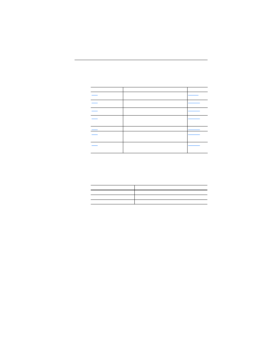
Parameter
Details
Reference
[Start Source]
Set to 5 “RS485 (DSI) Port” if Start is controlled from
the network.
[Speed Reference]
Set to 5 “RS485 (DSI) Port” if the Speed Reference is
controlled from the network.
[Comm Data Rate]
Sets the data rate for the RS485 (DSI) Port. All nodes
on the network must be set to the same data rate.
[Comm Node Addr]
Sets the node address for the drive on the network.
Each device on the network requires a unique node
address.
[Comm Loss Action] Selects the drive’s response to communication problems.
[Comm Loss Time]
Sets the time that the drive will remain in
communication loss before the drive implements A105
[Comm Loss Action].
[Comm Format]
Sets the transmission mode, data bits, parity and stop
bits for the RS485 (DSI) Port. All nodes on the network
must be set to the same setting.
Modbus Function Code (Decimal)
Command
03
Read Holding Registers
06
Preset (Write) Single Register
16 (10 Hexadecimal)
Preset (Write) Multiple Registers