Typical system wiring – single door (model 1511s), Display modes – SDC 1511T EXIT CHECK DELAYED EGRESS EMLOCK User Manual
Page 6
P:\INSTALLATION INST\Delayed Egress\INST-1511ST\INST-1511ST.vsd Rev G3 10-13 Page 6
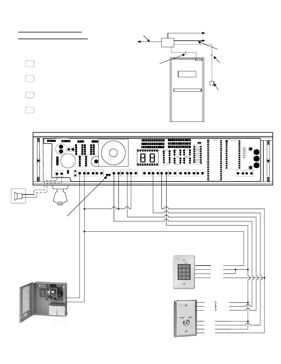
Typical System Wiring –
Single Door (Model 1511S)
3 or 5
conductors
8 or 10
conductors
Power
Supply
To Fire Panel
AC Mains
2 conductors
PUSH UNTIL ALARM
SOUNDS. DOOR CAN BE
OPENED IN 15 SECONDS.
Key Switch or
Access Control
(Optional)
To Smoke
Detection System
2 conductors
600 Series
Power Supply
+
-
+
-
728U or 728UL3
Key Switch
Reset Station
(OPTIONAL)
RED
GRN
BLK
WHT
BLK
BLU
RED
L3
OPTION
101-SP
Remote
Speaker
(OPTIONAL)
C NC
-
+
-
+
NC NO
NO C
C NC
NO C
NO C
NO C
NO C
NO C
NC NO
C NC
[ BAS ]
[ DPS ]
[RESET]
[RM TRIG]
[REX]
[RED RLY]
[GRN RLY]
[ LOCK ]
[ FP ]
[ PWR ]
J6
J7
J2
[IBO]
[EXT SPKR]
REMOVE J6 ONLY IF A FIRE
PANEL OR SMOKE DETECTION
SYSTEM IS CONNECTED TO
[FP] INPUT (Pg. 9)
918
Digital Keypad
+
-
C
NO
(OPTIONAL)
Display Modes
Door armed and locked.
Alarm countdown has ended,
door is unlocked and alarm sounding
until reset.
Door unlocked and alarm is shunted
(REX or Bypass)
Door has been opened after REX,
Bypass or Alarm.
15
00
- -
- -
- -
- -