Lock adjustment and operation – SDC 1511T EXIT CHECK DELAYED EGRESS EMLOCK User Manual
Page 12
STEP 1. After the lock has been mounted to the door and frame per the provided template, feed the wiring
through the access hole and out to the controller board. Re-install the lock front cover onto the lock. Ensure that
the trigger sensor is aligned with the hole in the cover. The sensor is preset at the factory to slightly project through
the cover.
WARNING: DO NOT ATTEMPT TO ADJUST THE TRIGGER SENSOR LENGTH. AS THIS WILL RESULT IN
DAMAGE TO THE SENSOR AND VOID THE WARRANTY.
STEP 2. Make all wiring connections to the lock. Observe the polarity of the input power terminals. The lock
senses the power supply voltage and automatically configures itself for 12vdc or 24vdc operation. Correct power
supply voltage must be used for proper lock operation.
WARNING: INPUT TERMINALS FOR RESET, REX AND
REMOTE TRIGGER MUST ONLY BE CONNECTED TO A NORMALLY OPEN MOMENTARY DRY CONTACT SWITCH (I.E.
928 DIGITAL KEYPAD OR 728 KEY SWITCH). CONNECTION TO A VOLTAGE OR A “WET” OUTPUT MAY DAMAGE THE
LOCK AND VOID THE WARRANTY.
STEP 3.
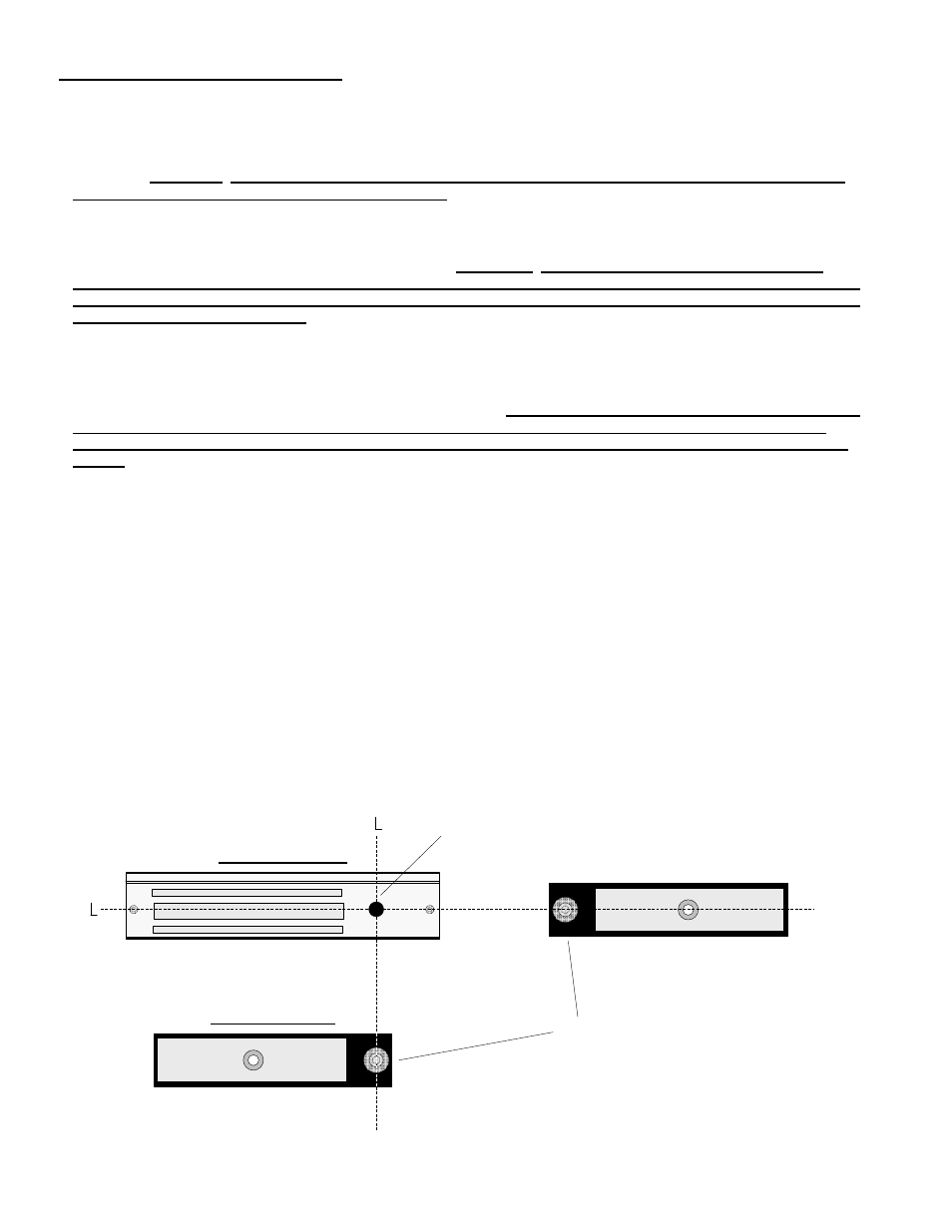
Slowly swing the door closed and visually observe the position of the armature trigger as it approaches
the trigger sensor on the lock. If the provided mounting template was used during the lock and armature installation,
the trigger & sensor should align with one another both horizontally and vertically. The LED on the back of the
trigger sensor will light when the armature trigger is detected.
IMPORTANT: CORRECT OPERATION OF THIS LOCK
DEPENDS ON THE TRIGGER SENSOR BEING ABLE TO DETECT THE ARMATURE TRIGGER WHEN THE DOOR IS
CLOSED. A PROXIMITY ADJUSTMENT CAN BE MADE TO THE TRIGGER FOR FINE TUNING. THIS IS EXPLAINED IN
STEP 4.
STEP 4. After alignment has been verified, close the door and apply power to the lock. The digital display will
show a two bars “- -“ indicating that the lock is in the Manual Power Up mode. Push on the door to verify that the
door is unlocked. Reset the lock at this time by turning the built in key switch clockwise or by triggering the remote
reset input. The lock should now secure the door and the LED display will show the delay time . You may change
the mode to Auto Power Up by setting the #6 dipswitch to the ON position. Now when you first apply power, the
door will be secure and the LED display will display the delay time without having to reset the lock.
STEP 5. Activation of the 1511S can be made by door movement or an external trigger. When using the door
movement method, activation is achieved through the way the armature hardware is designed. When someone
unlatches the door and applies up to 15 lbs. pressure, the lock will hold onto the armature while simultaneously
letting the door & trigger armature move away from the lock & trigger sensor. Sensitivity in the detection of the
trigger movement can be adjusted for optimum sensitivity & performance. This adjustment can be made by using
the 5mm hex wrench provided with the lock. The center of the trigger or “target” is spring loaded and can be
screwed in and out of the armature thus either decreasing or increasing the space between itself and the sensor.
The “spring” feature of the target is to prevent damage from direct contact with the trigger sensor. Depending on the
accuracy of the alignment, the trigger does not have to physically touch the sensor to operate correctly.
TRIGGER SENSOR
TRIGGER
HORIZONTAL
ALIGNMENT
VERTICAL
ALIGNMENT
C
C
1511S LOCK BODY
1511S ARMATURE
1581S ARMATURE
Lock Adjustment and Operation
P:\INSTALLATION INST\Delayed Egress\INST-1511ST\INST-1511ST.vsd Rev G3 10-13 Page 12