Maintenance/service – MacDon 742 HAY CONDITIONER User Manual
Page 73
Form # 46290
Issue 09/05
71
MAINTENANCE/SERVICE
Drive Roller Maintenance
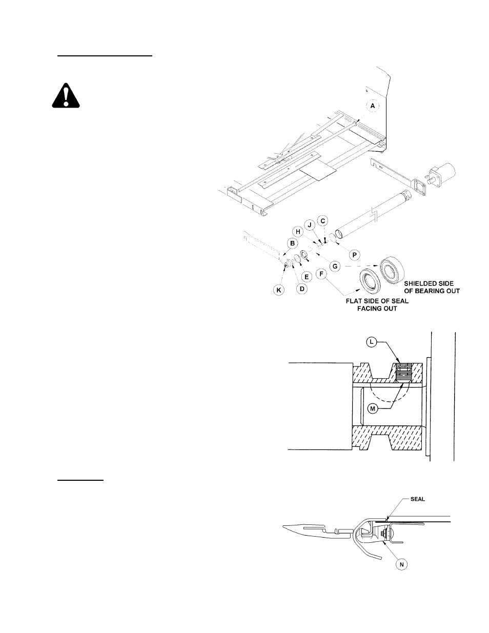
To replace drive roller bearings:
1. Raise header and reel.
CAUTION: Engage header lift cylinder stops
and reel props before working under header
or reel.
2. On 21’ to 36’ headers, position deck so drive
roller is easily accessible.
3. Loosen and uncouple draper.
4. If drive roller is at end of header, remove drive
roller assembly by sliding spring rod (A)
through hole in backsheet and pulling roller
out. (Loosen hose clamps to allow slack in
hydraulic hoses.)
If drive roller is at center opening,
remove the bolt holding rear bar in deck
and remove roller assembly.
5. Remove bearing assembly from roller
tube by tapping on arm at (B) while
holding roller. Disassemble by removing
bolt (C). NOTE: Retaining disk (P)
remains inside roller tube.
6. Clean inside of roller tube and stub shaft (D). Check tube
and stub shaft for wear or damage. Replace if necessary.
7. Place retaining ring (E) onto stub shaft (D) and hang it
loosely over stub shaft mounting face.
IMPORTANT: Retaining ring must be in position on stub
shaft before installing bearing into tube.
8. Sub-assemble seal (F), bearing (G) and washer (H) onto
stub shaft and secure with lockwasher (J) and bolt (C).
IMPORTANT: Install seal (F) with flat face (with writing) out,
and install bearing (G) with shielded side out.
9. Remove grease fitting (K) and press on end of stub shaft to
install bearing sub-assembly into roller tube. Press in until
retaining ring (E) can be installed in groove inside tube. To
prevent damage to bearing, do not press the assembly
deeper than necessary.
10. Reinstall fitting (K) into stub shaft and grease until grease
appears past seal.
11. Reassemble drive roller into deck, re-couple and tighten
draper.
NOTE: At drive roller to motor connection, there is a short
"through-bore" setscrew (L) on top of setscrew (M). When
removing, be sure to engage Allan wrench only far enough to
remove setscrew (L) first, then setscrew (M).
Deck Height
To prevent material from entering drapers and cutterbar,
maintain deck height so that draper runs just below cutterbar
with maximum 1/32” (1 mm) gap, or with draper deflected
down slightly [up to 1/16” (1.5 mm)] to create a seal.
Adjust as follows:
1. Loosen tension on drapers.
2. Lift draper up at front edge and loosen two nuts on deck
support (N), two or three per deck, depending on header
size.
3. Tap deck up or down relative to supports to achieve setting
recommended above.
4. Tighten deck support hardware and tension drapers.
DRIVE ROLLER TO MOTOR CONNECTION
DECK HEIGHT ADJUSTMENT