Operation – MacDon 742 HAY CONDITIONER User Manual
Page 28
Form # 46290
Issue 09/05
26
OPERATION
HEADER FLOTATION
IMPORTANT: To avoid frequent breakage of sickle components, scooping soil, or soil build-up at cutterbar in
wet conditions, header float should be set as light as possible without causing excessive bouncing.
Under normal conditions with cutterbar lowered (just off the ground), adjust float spring tension so 50 to 70 lbs.
of force (220 to 310 N) is required to lift cutterbar off ground at each end.
See "Header Flotation" in Windrower or Combine Adapter Operator's Manual for adjustment details.
NOTE: 30’ & 36’ Headers with gauge wheels use the
springs in the gauge wheel package to assist in
header floatation. As such, the windrower float
adjustment is different for these headers. Proceed as
follows:
1. 30’ Single Sickle Header: With gauge wheels
installed with dual springs on left hand side and
single spring on right hand side, adjust float spring
drawbolt dimension (A) on tractor to approximately
5.1 in. (130 mm) on the left side and 3.7 in. (95
mm) on the right side.
30’ Double Sickle & 36’ Header: With gauge
wheels installed with dual springs on both sides,
adjust float spring drawbolt dimension (A) on
tractor to approximately 3.5 in. (90 mm) on the left
side and 5 in. (125 mm) on the right side.
NOTE: For 36’ headers, one of the left-hand dual
springs on the tractor must have auxiliary inner
spring installed. For auxiliary inner spring kit order
B 2773.
NOTE: For 36’ Double Sickle headers,
four kits B 2773 are required.
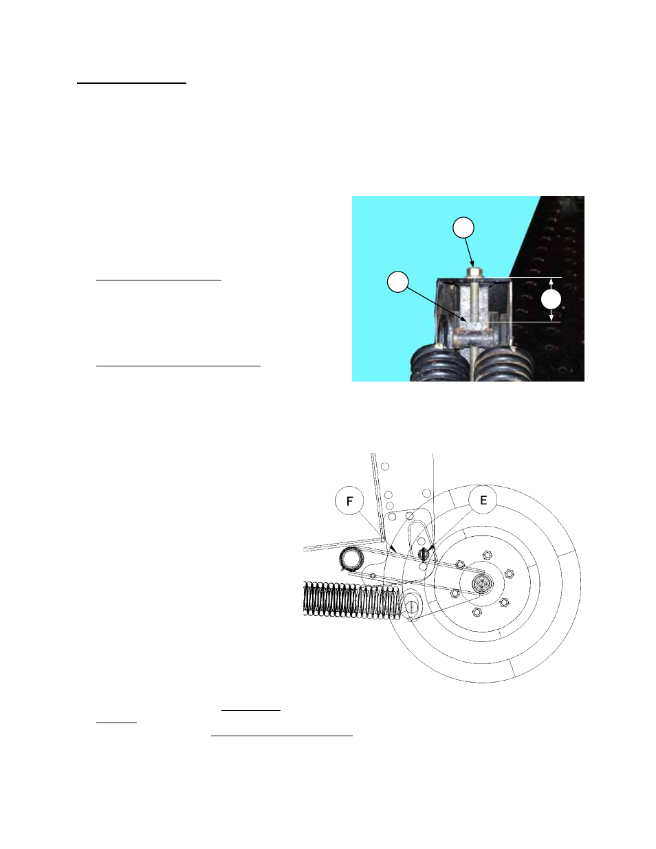
2. Set gauge wheels to medium stubble
height position (E).
3. Set center link to approximately 21.5 in.
(545 mm) pin to pin.
4. Adjust tractor float spring drawbolts
such that gauge wheel arm (F) contacts
pin (E) when the header is lowered. If
header floats away from the pin, reduce
float [increase dimension (A)]. If arm (F)
contacts pin but float is heavy, increase
float [decrease dimension (A)].
5. To adjust float:
• Raise header fully, shut off engine and
remove key.
• Loosen nut (C).
• Turn spring drawbolt (B) clockwise to
increase float (which makes header lighter when lowered to ground).
• Turn spring drawbolt (B) counter-clockwise to decrease float (which makes header heavier when lowered
to ground).
• Tighten nut (C) to lock the position.
• Lower header fully and check float at both ends of cutterbar. Force required to lift cutterbar should be
approximately the same at both ends.
GAUGE WHEEL
FLOAT ADJUSTMENT - WINDROWER
B
A
C