Unloading & assembly – MacDon 742 HAY CONDITIONER User Manual
Page 107
Form # 46290
Issue 09/05
105
UNLOADING & ASSEMBLY
INSTALL DRAPERS (continued)
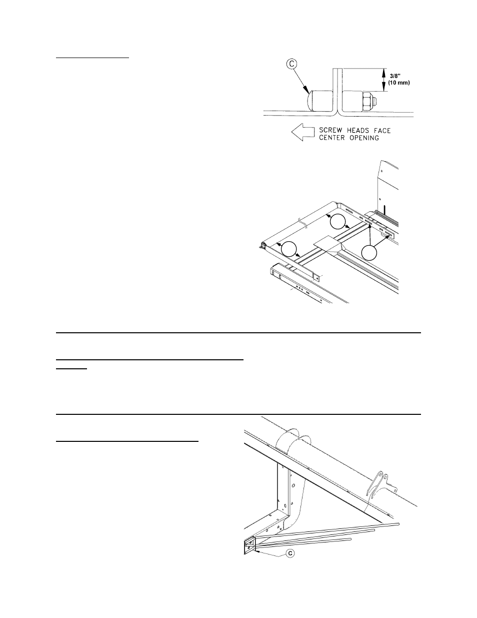
4. Connect draper with screw heads (C) facing
center opening.
NOTE: Place connector tube so holes closest
to end of tube are at the cutterbar.
5. Ensure V-guide on underside of draper
engages grooves at rear of both rollers.
6. Check draper to cutterbar clearance. Maximum
gap is 1 mm. If adjustment is required, see
“Deck Height” on page 71.
7. Apply draper tension until white indicator bar is
partially hidden behind roller support arm. See
"Draper Tension Adjustment" in Maintenance
/Service section of Operator's Manual.
8. Position decks to dimension (X) (see chart on
previous page) for desired opening width. See
"Delivery Opening Width" in Operation section
of Operator's Manual.
9. Align rollers for proper draper tracking. Adjust
hardware in slots (D) at the fixed roller rear
support. See page 70 for details:
12’ to 25’ Headers – equal front and rear.
30’ & 36’ Headers – Dimension (B) 3 mm
(1/8”) less than Dimension (A).
INSTALL COUPLER ON HEADER REEL LIFT HOSE
21' & 25'
Install quick coupler supplied with windrower or
combine adapter package on reel lift hose at left of
delivery opening.
ATTACH FORMING RODS (OPTIONAL)
Attach forming rods (C) to left and right header
legs.
NOTE: Longer rod goes on top, and bolt heads go
inside header leg.
Forming rods are used in windrowing applications
only, and are not used with hay conditioner.
CONNECTOR SCREW HEADS
ATTACH FORMING RODS
FIXED ROLLER ALIGNMENT
(NARROW OPENING & IDLER ROLLER SHOWN)
A
B
D