Orbital Antares User Manual
Page 86
Antares
®
OSP-3
User’s Guide
Section 8.0
– Non-Standard Services
Release 1.1
July 2013
75
launches from KLC having conducted the first ever launch from KLC on the atmospheric interceptor tech-
nology (ait) program, multiple target vehicles, and two successful Minotaur IV vehicles. The layout of the
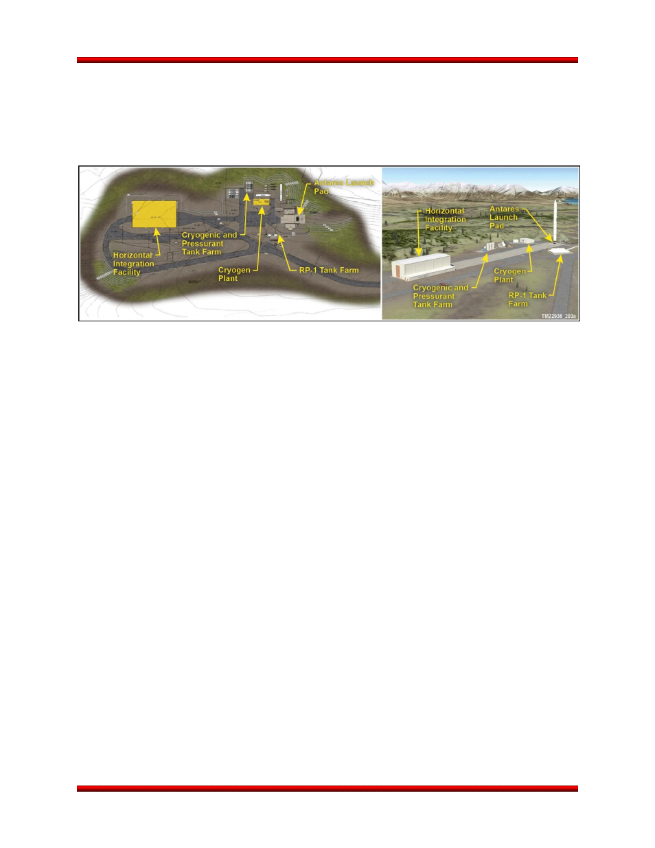
Antares facilities at KLC is provided in Figure 8.19-1. The launch pad design is nearly identical to the An-
tares pad at WFF. The HIF design, while resized to meet the expected launch rate, fully meets Antares
requirements.
Figure 8.19-1. Layout of the Antares Facilities at KLC
The general approach for conducting Antares launches from KLC mirrors the concept of operations at
WFF; thereby, minimizing technical and schedule risk from baseline Antares processes. The current An-
tares GSE that is in use at WFF functions in the exact same manner at KLC. Following subsystem testing
and acceptance, the major Antares subsystems ship to the KLC HIF for final assembly and checkout. Or-
bital subsystems manufactured and tested in Orbital’s Chandler, Arizona facilities, including the avionics
section and the composite structures, ship directly to the HIF for integration. The CASTOR 30 second
stage motor and Stage 1 engines also ship directly to KLC. As with the transport to WFF, the large An-
tares core stage ships by sea to Alaska. Truck transport of the core from the Kodiak port to the launch
site was analyzed and demonstrated with a mock-up with no major obstacles encountered. Furthermore,
a plan was developed to handle the expendable commodities in Alaska.
The current indirect launch support facilities on Kodiak (e.g., the PPF, storage facilities, etc.) were sized
for a medium class launch vehicle, and support Antares-sized payloads and logistics well.