Orbital Antares User Manual
Page 15
Antares
®
OSP-3
User’s Guide
Section 2.0
– Overview
Release 1.1
July 2013
4
the Antares vehicle, are largely derived from structures and systems used on the Zenit series of launch
vehicles, which have extensive flight heritage including more than 60 successful launches.
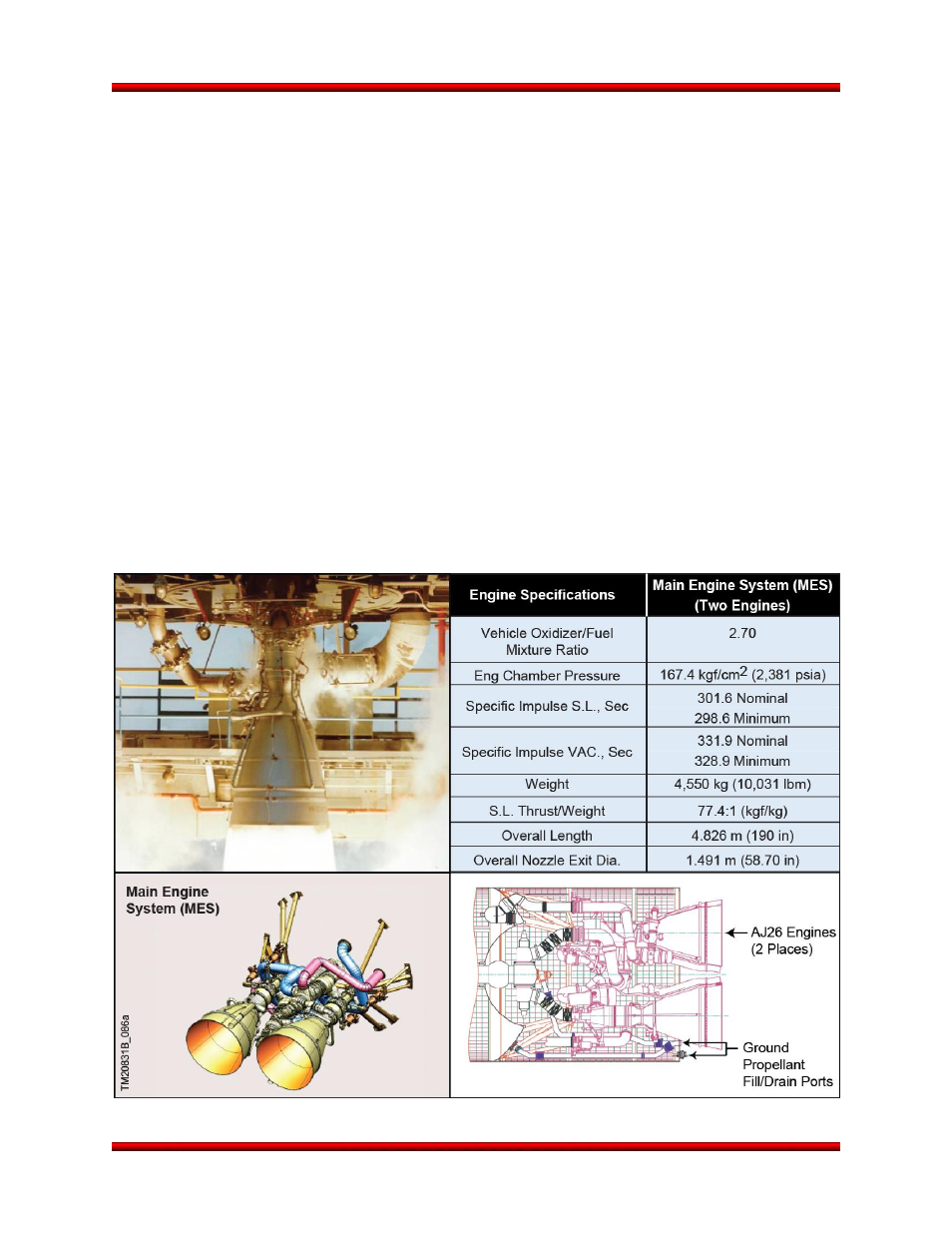
The Stage 1 aft bay contains the MES and is the primary interface between the launch vehicle and
ground systems. Many of the mechanical, fluid, and electrical interfaces connect through the aft bay
structure. These connectors mate with a launch ring that mounts to the vehicle in the integration building
while the launch vehicle is horizontal. This permits all flight separation connections to be mated and veri-
fied inside the integration facility prior to transporting to the pad.
The MES, shown in Figure 2.2.1-1, generates thrust for launch vehicle motion and control during Stage 1
ascent. The MES consists of two AJ26 LOX/RP rocket engines that supply approximately 3,630 kN
(816,000 lbf) total vacuum thrust mounted on a thrust frame. The two Aerojet AJ26 engines are modified
Russian NK-33 engines originally designed and produced for use on the Russian N-1 launch vehicle.
The engines use an oxygen-rich, staged combustion cycle that can throttle from 58% to 108%, and has a
variable mixture ratio valve for controlling relative flow rates of oxidizer and fuel. These engines are op-
erational, well characterized, and have an extensive test history. Each of the AJ26 engines, refurbished
with modern components, undergoes hot-fire acceptance testing at the test stand at the NASA Stennis
Space Center prior to integration onto the vehicle.
Figure 2.2.1-1. Antares Main Engine System