Orbital Antares User Manual
Page 47
Antares
®
OSP-3
User’s Guide
Section 5.0
– Payload Interfaces
Release 1.1
July 2013
36
5.2.3. Mechanical Interface Control Drawing (MICD)
All mechanical interfaces between the payload and Antares are defined in the mission ICD and a mission-
specific MICD. The MICD is a dimensional drawing that captures the payload interface details, separa-
tion system, payload static volume within the fairing, and locations of the access doors. Orbital provides
a toleranced MICD to the customer to allow accurate machining of the spacecraft fastener holes to the
payload interface.
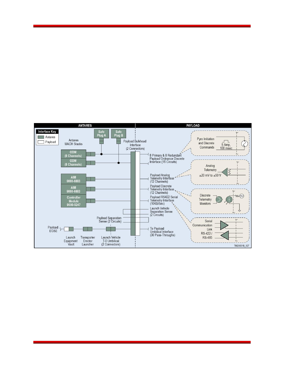
5.3. Electrical Payload Accommodation Requirements
The Antares payload electrical interface, shown in Figure 5.3-1, supports battery charging, external pow-
er, discrete commands, discrete telemetry, analog telemetry, serial communication, payload separation
indications, and ordnance events using configurable flight qualified avionics components. Two 61-pin
electrical connectors located at the launch vehicle interface plane at clocking angles 45° and 225° provide
the standard electrical interface.
Figure 5.3-1. Antares Electrical Interface Block Diagram
Ordnance Discretes: Antares provides sixteen redundant pyrotechnic circuits through two dedicated
MACH Ordnance Driver Module (ODM). Each ODM provides drivers capable of 0.3 to 13 Amps, at
100 ms, with a timing accuracy within 1 ms into a 1.0 ohm or greater bridgewire initiation device at 26 to
34 volts. All pyrotechnic driver channels can be fired simultaneously with a timing accuracy of 1 ms be-
tween channels. Simultaneous firings of up to four ordnance events into 1.0 ohm bridgewire initiation de-
vices have been demonstrated. In addition, the ODM channels provide 26 to 34 volts to trigger high im-
pedance discrete events, if required. Safing for all payload ordnance events is accomplished through pri-
mary and redundant arming plugs, which are accepted by range safety organizations as valid hardware
inhibits.