Orbital Antares User Manual
Page 16
Antares
®
OSP-3
User’s Guide
Section 2.0
– Overview
Release 1.1
July 2013
5
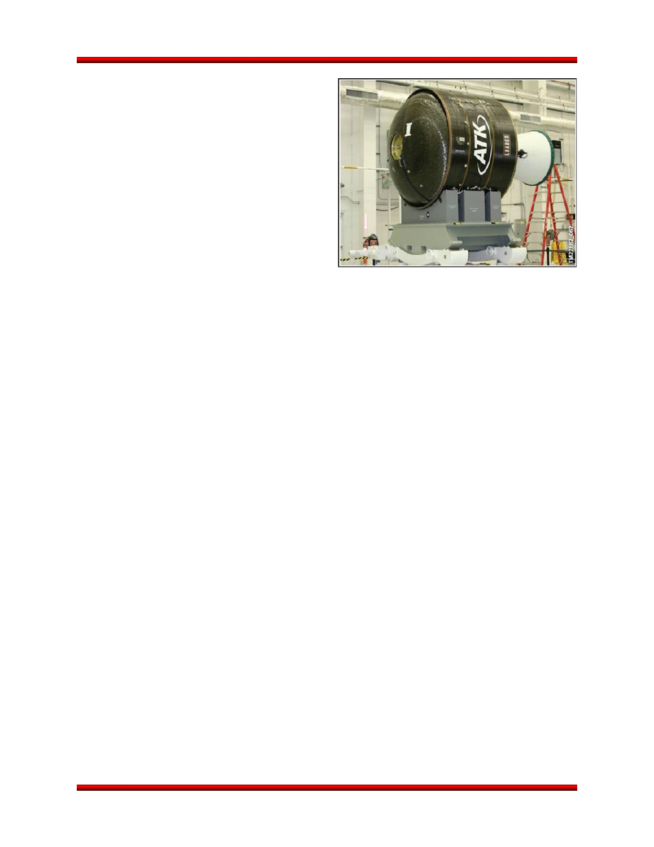
2.2.2. Stage 2 Assembly
Orbital uses the CASTOR 30 family of SRMs as the
second stage for the Antares vehicle (Figure 2.2.2-
1). The CASTOR 30 product line is derived from the
heritage CASTOR 120 motor used on the Taurus
launch vehicle. The CASTOR 30 motors, manufac-
tured by ATK, consist of a composite graphite/epoxy
wound case and a flexseal design at the throat to
allow for two-axis Thrust Vector Control (TVC) mo-
tion during flight. Orbital supplies a composite
sandwich structure motor adapter cone to provide a
structural load path from the Stage 1 forward skirt to
the CASTOR motor aft skirt.
Antares utilizes variants of the CASTOR 30 motor to
meet the requirements of specific missions. The baseline Antares service for OSP-3 will use the CAS-
TOR 30B motor (Antares 120). An enhancement offered includes the CASTOR 30XL motor (Antares
130). Both the CASTOR 30B and CASTOR 30XL motors are derived from the CASTOR 30 but are mod-
ified for increased performance and to increase commonality with other ATK products.
2.2.2.1. Attitude Control System (ACS)
The Antares ACS provides three-axis attitude control throughout boosted flight and coast phases. The
MES provides yaw, pitch, and roll control during Stage 1 powered flight. Stage 1 flies a pre-programmed
attitude profile based on pre-flight trajectory design and optimization.
Stage 2 flight is controlled by the combination of the CASTOR 30 TVC and the onboard Attitude Control
System (ACS) discussed in the following paragraph. Stage 2 is guided by the Powered Explicit Guidance
algorithms that compute the trajectory based on the vehicle state just after Stage 1 separation and pre-
programmed orbital targets. The algorithm first computes the required coast period between Stage 1 se-
paration and Stage 2 ignition, and then computes the attitude profile to be used during the burn. An in-
plane or out-of-plane turning scheme is used to manage any excess energy to minimize insertion errors.
The Stage 2 ACS employs a cold gas nitrogen system
with heritage from Orbital’s other space launch
vehicles. During the Stage 1/2 coast period and after Stage 2 burnout, the vehicle's attitude is controlled
by this ACS system. The cold-gas control system is also used during the Stage 2 burn to control roll atti-
tude and rate, and to orient the payload for separation. Following payload separation, the cold-gas con-
trol system is used to orient Stage 2 for collision avoidance and prevent payload contamination from resi-
dual by-products of the Stage 2 motor.
Figure 2.2.2-1. CASTOR 30B Motor