Orbital Antares User Manual
Page 32
Antares
®
OSP-3
User’s Guide
Section 4.0
– Payload Environments
Release 1.1
July 2013
21
4. PAYLOAD ENVIRONMENTS
This section provides details of the predicted environmental conditions that the payload experiences
during Antares ground operations, powered flight, and post-boost operations. The environmental
conditions presented in this section are representative of a typical mission and are applicable to the
baseline Antares 120 unless specifically noted. Orbital performs mission-specific analyses as part of the
standard Antares launch service to determine payload environments for a specific mission. These results
are documented in compliance with the mission ICD.
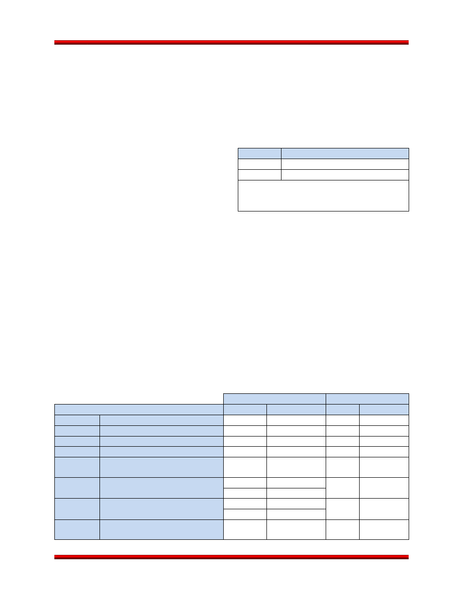
4.1. Design Limit Load Factors
Design limit load factors due to the combined ef-
fects of steady state and low frequency transient
accelerations are defined in Table 4.1-1 for Antares
configurations 120, 121, 130, 131, and 132. These
values apply to the payload CG, account for maxi-
mum ground and flight loads, and include uncer-
tainty margins.
Antares 122 is the single exception to the axial acceleration limit shown in Table 4.1-1. For this configu-
ration, the axial design limit load factor of +8.0g may be reached during third stage operation.
In order to minimize loads and deflections as well as the potential for coupling with the launch vehicle
guidance system, the first bending frequency of the payload assuming a fixed base must be maintained
above 8 Hz. Dynamic response is largely governed by payload characteristics, so mission-specific
coupled loads analyses must be performed in order to provide precise load predictions. Results are
documented in the mission-specific ICD.
4.1.1. Time-Phased Acceleration Loads
Dynamic loading events that occur throughout various portions of the ground operations and flight include
steady state acceleration, transient low frequency acceleration, acoustic impingement, random vibration,
and pyroshock events. During ground and flight operations, the typical maximum steady state accelera-
tions experienced at the payload interface are as shown in Table 4.1.1-1. Coupled Loads Analyses
(CLAs) are performed for each mission to define maximum predicted acceleration for a specific payload.
Table 4.1.1-1. Typical Antares 120 Ground and Flight Acceleration Loads at the Payload Interface
Axial
Lateral
Load Case
Static
Transient
Static
Transient
Ground
Payload Vertical
-1.0
±0.5
0.0
±0.5
Ground
Payload Horizontal
0.0
±0.4
-1.0
±0.3
Flight
Liftoff
1.3
±0.5
0.0
±0.5
Flight
Transonic
2.0
±0.3
0.2
±0.7
Flight
Stage 1
Maximum
6.0
±0.5
0.0
±0.5
Flight
Main Engine Cut Off
4.8
±0.4
0.0
±0.5
0.8
±1.3
Flight
Stage 2 Ignition
0.0
-0.8/ +1.5
0.0
±0.3
0.9
±0.3
Flight
Stage 2
Maximum
3.7
±0.3
0.0
±0.3
Table 4.1-1. Design Limited Load Factors
Axis
Maximum Acceleration (g)
Axial
-1.0/+6.5
Lateral
±1.5
Notes:
1) Sign Convention: Positive Axial Acceleration Produces
Compression.
2) Axial and Lateral Accelerations Are Simultaneous.