Orbital Antares User Manual
Page 67
Antares
®
OSP-3
User’s Guide
Section 7.0
– Ground and Launch Operations
Release 1.1
July 2013
56
7.3. Launch Vehicle Processing
All major vehicle subassemblies are
delivered from either Orbital’s production facilities or directly from the
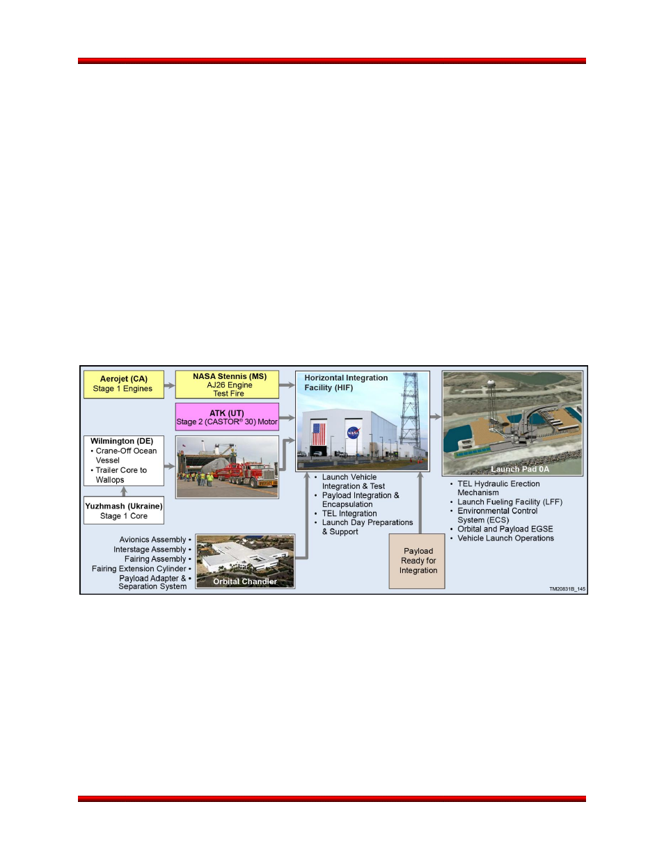
vendor to the HIF. Figure 7.3-1 depicts the typical flow of hardware from the factory to the launch site.
Once the major vehicle components and subassemblies are delivered to the HIF, the vehicle is horizon-
tally integrated and tested prior to the arrival of the payload. Integration is performed on platforms set at
convenient working heights, which allows relatively easy access for component installation, inspection
and test.
The transformation of engines, rocket motors, avionics, and sub-assembled structures into an integrated
launch vehicle occurs at the HIF. A small group of skilled engineers and technicians perform the follow-
ing major functions at this facility:
Receive and inspect all motors, rocket engines, subassemblies, and vehicle components
Integrate rocket engines and mechanical, electrical, ordnance components, and subassemblies to
the individual stages
Perform electrical testing of the integrated motors, composite subassemblies, and the avionics
section
Receive the payload, test interfaces, integrate the payload to the LV, and encapsulate the payl-
oad within the fairing
Figure 7.3-1. Flow of Antares Hardware to the Launch Site
7.3.1. Stage 1 Motor Core
Upon arrival at the HIF, the Stage 1 core is lifted from its overland transporter and placed on GSE using
HIF cranes. Functional checks are performed to validate electrical and pneumatic systems are properly
performing after the core’s transport. The aft bay of the core is removed providing access for avionics,
ordnance, and MES installations. Once the MES is mated the Stage 1 core, electrical, functional, and
leak checks are performed. Following this validation, the motor aft bay is reinstalled completing the Stage
1 Core subassembly.