Orbital Antares User Manual
Page 80
Antares
®
OSP-3
User’s Guide
Section 8.0
– Non-Standard Services
Release 1.1
July 2013
69
batteries that are used on other subsystems. The RF network, including the antennas and couplers, are
also directly leveraged and common with the existing Antares FTS subsystem. Skin mounted external
antennas mounted on the interstage are employed from pre-launch through interstage separation. Follow-
ing interstage separation, stand-off plate-mounted antennas on the ACS deck are used through end of
mission.
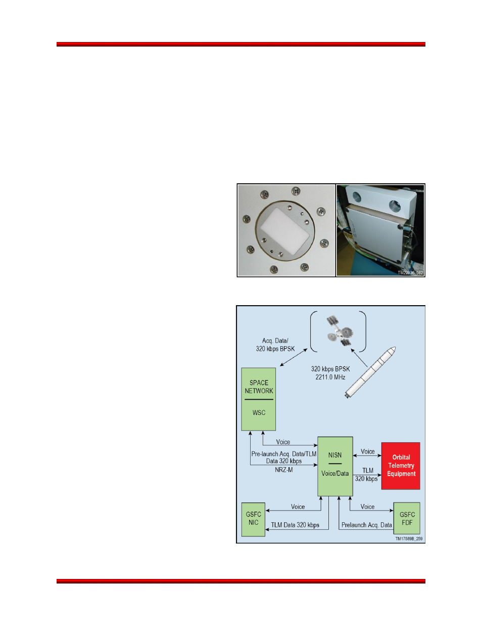
8.8. Over the Horizon Telemetry
Orbital offers a Telemetry Data Relay Satellite System (TDRSS) interface that can be added to Antares
as an enhancement to provide real-time telemetry coverage during blackout periods with ground based
telemetry receiving sites. The TDRSS enhancement consists of a LCT2 TDRSS transmitter, one cavity
backed antenna (Figure 8.8-1), an RF switch, and associated ground test equipment. The RF switch is
used during ground testing to allow for a test
antenna to be used in lieu of the flight antennas
(which reside under the fairing in most configu-
rations, and therefore, cannot be operated once
the fairing is integrated). Near the time when
telemetry coverage is lost by ground based
telemetry receiving sites, the LV switches tele-
metry output to the TDRSS antenna and points
the antenna towards a TDRSS satellite. The
TDRSS satellite relays the telemetry to the
ground where it is then routed to the launch
control room (Figure 8.8-2). A phased array
antenna can be added as a non-standard, mis-
sion-specific enhancement to achieve higher
data rates. The TDRSS system proposed in-
cludes the launch vehicle design, analysis,
hardware and launch vehic
le testing. Orbital’s
system does not include the costs associated
with the Government-furnished TDRSS system
leasing and operation.
Antares Unique Considerations: In the An-
tares TDRSS application, the TDRSS pointing
requirements necessitate the addition of two
cold-gas nitrogen tanks to the configurable
Stage 2 ACS. These additional tanks maintain
the required cold gas margin for the system. For
some missions, it is possible that the pointing
requirements for the payload or other maneuv-
ers may conflict with the pointing requirements
to maintain TDRSS link margins. During these
brief periods, Antares will store and forward the
data to ensure complete telemetry coverage of
the entire mission.
Figure 8.8-1. TDRSS 20W LCT2 Transmitter and
UB S-Band Antenna
Figure 8.8-2. TDRSS Notional Telemetry Flow