Antares, Osp-3 user’s guide – Orbital Antares User Manual
Page 42
Antares
®
OSP-3
User’s Guide
Section 4.0
– Payload Environments
Release 1.1
July 2013
31
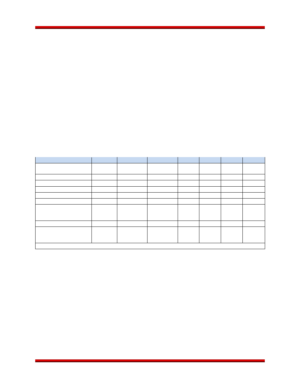
4.7. Payload RF Environment
As shown in Table 4.7-1, Antares has five RF sources: three S-Band transmitters at 2241.5, 2269.5, and
2288.5 MHz, respectively, and a C-Band Transponder that transmits at 5765 MHz. The fairing provides
attenuation for the payload RF environment produced by the external aft antennas until the fairing is dep-
loyed. Radiation inside the fairing, as a result of vehicle source radiation, is further limited through the
use of two sets of antennas. The aft antennas located on the vehicle interstage skin are used until fairing
separation. A second set of antennas, located inside the fairing, are used after fairing deployment. The
maximum field strength produced by these sources at the payload interface is 3.1 V/m in S-Band and
49.6 V/m in C-Band.
During ground and launch operations, the Range uses multiple radars to track the vehicle and a direc-
tional Ultra High Frequency (UHF) transmitter to capture the FTS receivers. Again, the payload fairing
provides some measure of attenuation of the RF fields from these sources. The maximum RF levels as-
sociated with range sources are actively managed to achieve less than 20 V/m at frequencies from
10 kHz to 1 GHz and 30 V/m from 1 to 40 GHz during launch and ascent. As lower levels are required to
protect the payload, Orbital will work to coordinate with the range to further limit RF power levels.
Table 4.7-1. Launch Vehicle RF Emitters and Receivers
SOURCE
1
2
3
4
5
6
7
Function
Command
Destruct
Tracking
Transponder
Tracking
Transponder
Launch
Vehicle
Launch
Vehicle
Launch
Vehicle
Location
Receive/Transmit
Receive
Transmit
Receive
Transmit Transmit Transmit
Receive
Band
UHF
C-Band
C-Band
S-Band
S-Band
S-Band
L-Band
Frequency (MHz)
421
5765
5690
2241.5
2288.5
2269.5
1575.42
Bandwidth (MHz)
0.18
14
14
3.56
3.56
3.56
20.46
Power Output
N/A
400 W (peak)
N/A
5 W*
5 W*
5 W*
N/A
Sensitivity
-107 dBm
N/A
-70 dBm
N/A
N/A
N/A
C/N
0
=
35.4 dB-
Hz
Modulation
Tone
Pulse Code
Pulse Code
PCM/FM PCM/FM PCM/FM
Phase
Maximum Field Strength at
Fwd Edge of the Payload
Adapter Cone
N/A
49.6 V/m
N/A
3.1 V/m
0.1 V/m
0.4 V/m
N/A
* WFF Baseline KLC Values May Be Higher