Orbital Antares User Manual
Page 39
Antares
®
OSP-3
User’s Guide
Section 4.0
– Payload Environments
Release 1.1
July 2013
28
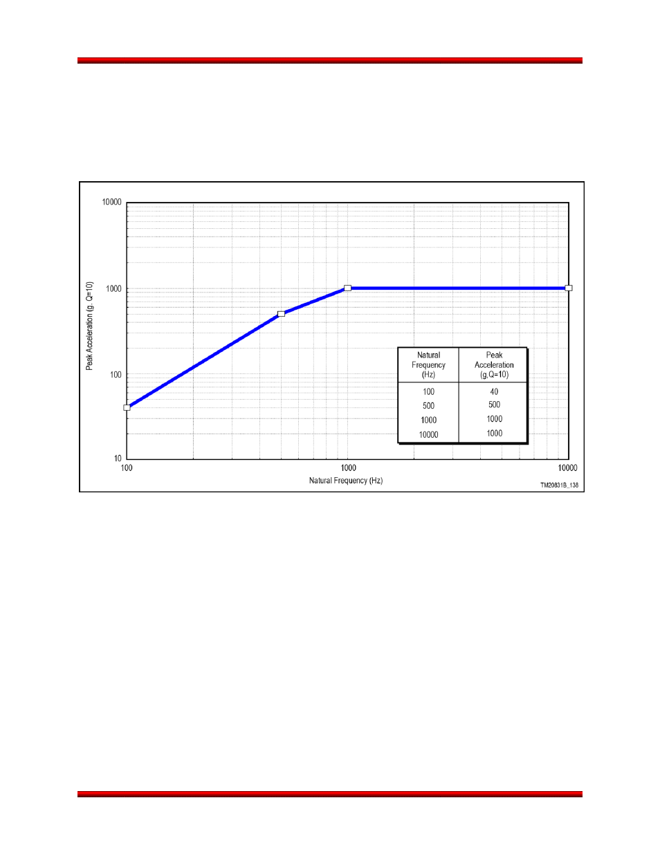
4.3. Payload Shock Environment
The maximum shock response spectrum at the base of the payload from all launch vehicle events will not
exceed the flight limit levels provided in Figure 4.3-1. The flight limit levels are derived from ground sepa-
ration test data and analytical predictions for the vehicle and payload separation systems. These levels
are applicable to a payload using the Antares optional payload separation system or attaching to the non-
separating interface.
Figure 4.3-1. Antares Payload Maximum Flight Level Shock at the Base of the Payload
See also other documents in the category Orbital Equipment:
- GMD Boost Vehicle (2 pages)
- GQM-163A Coyote (2 pages)
- Minotaur I (99 pages)
- Minotaur I (2 pages)
- Minotaur VI (2 pages)
- Minotaur IV (121 pages)
- Minotaur V (2 pages)
- Minotaur IV (2 pages)
- Minotaur-C (2 pages)
- Pegasus (2 pages)
- Pegasus (92 pages)
- Antares (2 pages)
- GEOStar-2 Bus (4 pages)
- GEOStar-3 Bus (2 pages)
- GEOStar Hosted Payloads (2 pages)
- SMF – Virginia (2 pages)
- SMF – Arizona (2 pages)
- LEOStar-3 Bus (4 pages)
- LEOStar-2 Bus (4 pages)
- Iridium NEXT (2 pages)
- Hingelock TEE Deployer Model 358 (2 pages)
- Hingelock TEE Deployer Model 5E9 (2 pages)
- Hingelock TEE Deployer Model 621 (2 pages)
- Hingelock TEE Deployer Model 625 (2 pages)
- Hingelock TEE Deployer Model 9843 (2 pages)
- Hingelock TEE Deployer Model T126 (2 pages)
- Overlap Dual-TEE Model 225 (2 pages)
- Overlap TEE Self-Deployer Model 1/2 OL-SD (2 pages)
- Overlap TEE Deployer Model 214 (2 pages)
- Wire Antenna Deployment Assembly Model 499 (2 pages)
- Wire Antenna Deployment Assembly Model 9842 (2 pages)
- Deep Space 1 (2 pages)
- Dawn (2 pages)
- RHESSI (2 pages)
- SORCE (2 pages)
- IBEX (2 pages)
- Coriolis (2 pages)
- FORMOSAT-3/COSMIC (2 pages)
- AIM (2 pages)
- Glory (2 pages)
- Landsat 8 (2 pages)
- OCO-2 (2 pages)
- ICESat-2 (2 pages)
- ICON (2 pages)