Antares, Osp-3 user’s guide – Orbital Antares User Manual
Page 14
Antares
®
OSP-3
User’s Guide
Section 2.0
– Overview
Release 1.1
July 2013
3
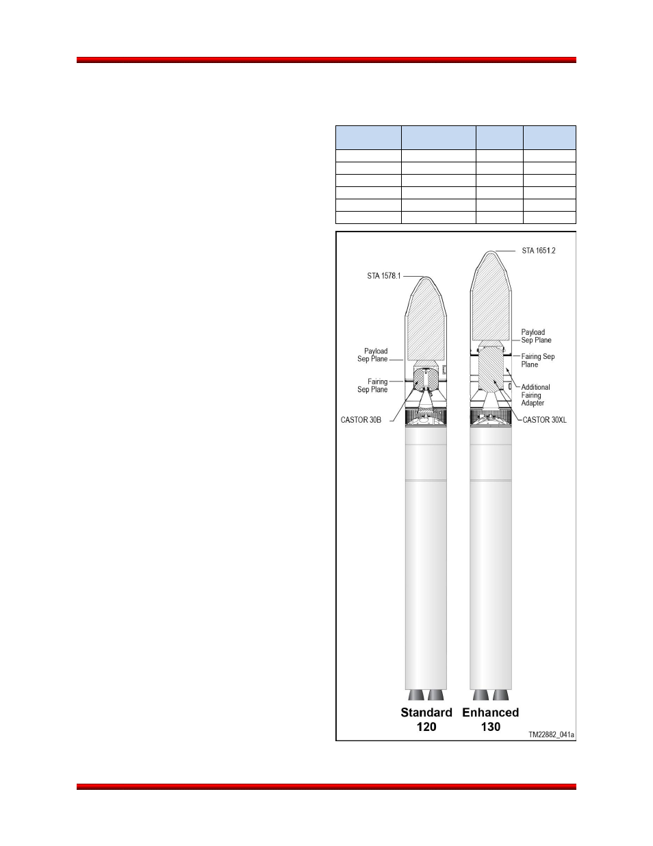
The Antares 120 configuration rocket is the baseline for OSP-3. The 130 is an enhancement off that
baseline. The Antares 120 and 130 configurations (Figure 2.2-2) utilize the CASTOR 30B and CASTOR
30XL SRM second stage, respectively, to provide
increased performance to Low Earth Orbit (LEO).
Both the CASTOR 30B and CASTOR 30XL second
stage motors, built by Alliant Techsystems, Inc.
(ATK), are based on the CASTOR 30 SRM. The
Antares 130 also includes a second 1860 mm (73.3
in) tall fairing adapter to accommodate the addition-
al length of the CASTOR 30XL SRM. This adapter
allows Orbital to offer the same payload fairing dy-
namic and static envelopes for both the Antares 120
and 130 configurations.
For missions with stringent orbit insertion require-
ments, improved insertion accuracy is provided with
Orbital’s optional Bi-Propellant Third Stage (BTS) on
Antares 121 and 131 configurations. The accuracy
achievable by the BTS is limited only by any accu-
mulated navigation errors during flight, which are
dependent on the mission timeline and trajectory
chosen. An optional 3-
axis stabilized STAR™ 48BV
third stage is also available on Antares 122 and 132
configurations, which provides a significant perfor-
mance increase for payloads with high-energy orbit
requirements. These optional third stages are de-
scribed in greater detail in Section 8 of this guide.
2.2.1. Stage 1 Assembly
The Stage 1 Assembly consists of the Stage 1 pro-
pellant tanks and the Main Engine System (MES). It
also incorporates the Range-required Flight Termi-
nation System (FTS). Stage 1 establishes the 3.90
m (154 in) diameter of the Antares launch vehicle
and is 27.6 m (90.6 ft) long.
The Stage 1 core facilitates the storage, manage-
ment, and delivery of propellants (LOX and kero-
sene RP) to the MES at required conditions and
flow rates. The Stage 1 core includes propellant
tanks, pressurization tanks, valves, sensors, FTS,
feedlines, tubing, wiring and other associated hard-
ware. The Stage 1 core structures and associated
propellant systems are manufactured by the Yuzh-
mash State Enterprise under the design authority of
State Design Office Yuzhnoye, both in the Ukraine.
The Stage 1 systems, while specifically designed for
Figure 2.2-2. Antares 120 and 130
Configurations
Table 2.2-1. Antares Numbering Conventions
Vehicle
Identifier
Stage 1
Stage 2
(CASTOR)
Stage 3
120 (Baseline)
LOX/RP, AJ26
30B
None
121 (Enhanced)
LOX/RP, AJ26
30B
BTS
122 (Enhanced)
LOX/RP, AJ26
30B
STAR 48BV
130 (Enhanced)
LOX/RP, AJ26
30XL
None
131 (Enhanced)
LOX/RP, AJ26
30XL
BTS
132 (Enhanced)
LOX/RP, AJ26
30XL
STAR 48BV