MTS Series 215 Rotary Actuator User Manual
Page 59
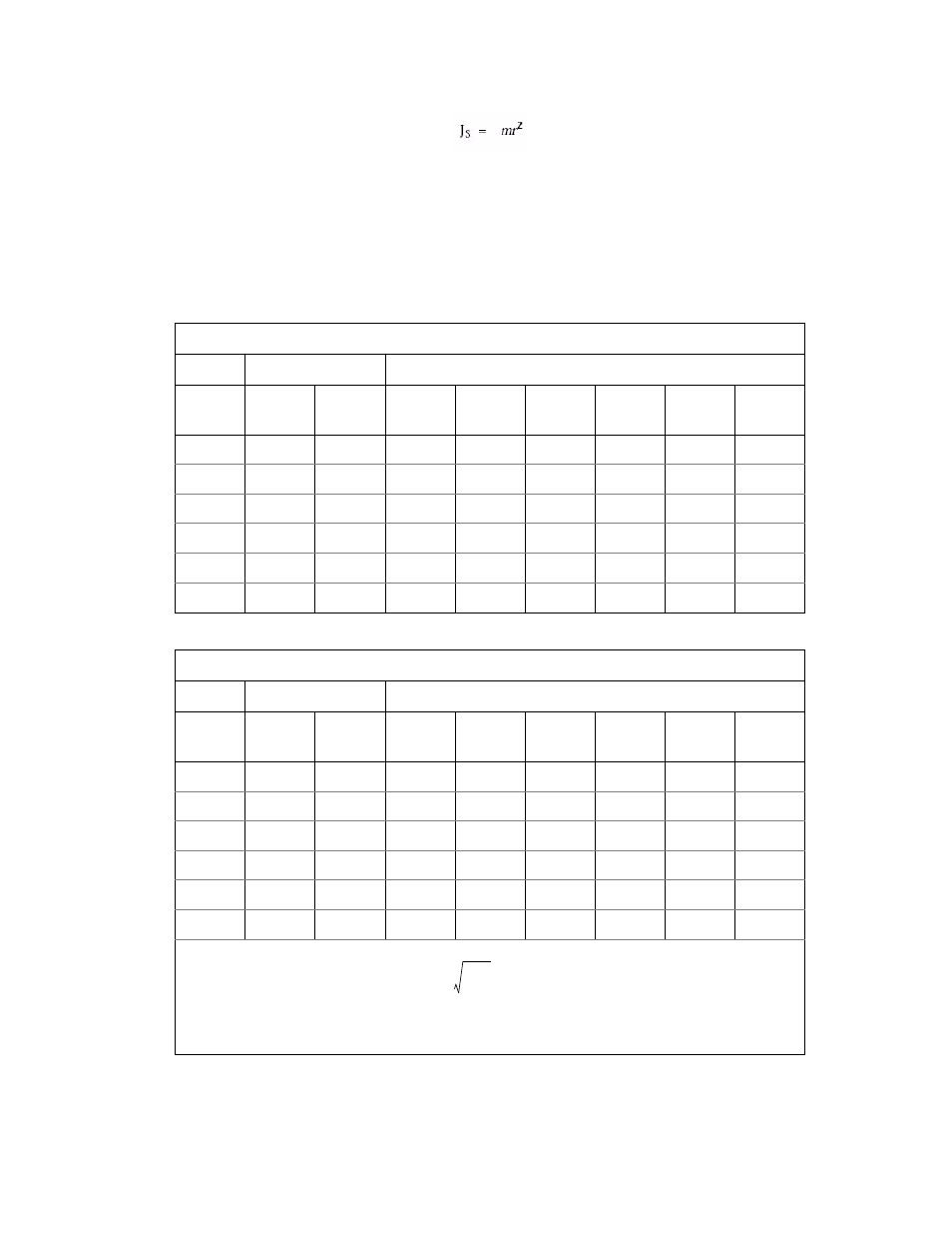
Determining Maximum Rotational Inertia (JT)
Series 215 Rotary Actuator Product Manual
Operation
59
3. After calculating the total rotational inertia (J
T
), compare the value to the
maximum allowable J
T
for the specific actuator and servovalve combination
indicated in the following. If the maximum allowable J
T
is exceeded, the
test setup must be altered to reduce the total rotational inertia or an
additional restraint must be provided to keep the actuator rotor vane from
impacting the internal actuator rotor vane stops at full velocity.
Maximum Allowable Rotational Inertia (J) When Using Only Internal Actuator Rotor Vane Stops
U.S. C
USTOMARY
S
ERVOVALVE
F
LOW
M
AX
J
FOR
A
CTUATOR
M
ODEL
(
LBM
·
IN
.
2
)
M
ODEL
R
ATED
(
GPM
)
P
EAK
*
(
GPM
)
215.32
215.35
215.41
215.42
215.45
215.51
252.23
5.00
9
39
302
1825
32905
305558
3020992
252.24
10.00
17
--
76
456
8226
76389
755248
252.25
15.00
26
--
34
203
3656
33951
335666
252.31
25.00
43
--
--
73
1316
12222
120840
256.04
40.00
70
--
--
--
514
4774
47203
256.09
90.00
156
--
--
--
--
943
9324
SI M
ETRIC
S
ERVOVALVE
F
LOW
M
AX
J
FOR
A
CTUATOR
M
ODEL
(K
G
·
M2
)
M
ODEL
R
ATED
(L/
MIN
)
P
EAK
* (L/
MIN
)
215.32
215.35
215.41
215.42
215.45
215.51
252.23
19.00
33
0.01
0.09
0.54
9.67
89.49
884.89
252.24
37.00
64
--
0.02
0.13
2.42
22.37
221.22
252.25
56.00
97
--
0.01
0.06
1.07
9.94
98.32
252.31
93.00
161
--
--
0.02
0.39
3.58
35.40
256.04
151.00
262
--
--
--
0.15
1.40
13.83
256.09
340.50
589
--
--
--
--
0.28
2.73
* Flow through the valve at 3,000 psi (∆P). Using reduced system pressures (∆P) will
decrease peak flow Q peak = Q rated
Decreasing peak flow will allow an increase in acceptable inertia (J). Refer to “Series 215
Rotary Actuator Ratings by Model” for the maximum velocity into vane stops where W= Q
peak x 3.85 in.3/sec Displacement in.3/rad.
ΔP
1000
------------