Sample calculation – MTS Series 215 Rotary Actuator User Manual
Page 51
Test Setup Using Diaphragm Flexures
Series 215 Rotary Actuator Product Manual
Operation
51
Sample calculation
The previous figure illustrates the forces and measurements pertinent to the
calculations. Refer to the appropriate tables for ratings and dimensions of the
Model 215.45 Rotary Actuator used in the example. The following calculations
use values derived from the sample calculations performed previously.
Using the preceding formulas and following values calculate
Δ (centerline offset)
and then
θ (angle of flex on flexures). If θ is not greater than θ
F2
, the flexures are
adequate (from Table 1-7,
θ
F2
= M).
Calculate S
B
and determine if it is within acceptable limits for the specific
test.
a = 11.75 in. (Distance from actuator center line to base plate center)
k
1
= 148.5 x 10
6
lbf-in./rad. (Torsional stiffness of thin flat plate)
L
1
= 43 in. (Length of base plate subjected to twisting)
Note
Length of base plate subject twist has been changed from 37 in. to 43 in.
This was necessary because using diaphragm flexures at the ends of a
specimen increases the distance between the foot mounting and
reaction bracket. Refer to “Diaphragm Flexure Dimensions and Ratings”,
dimension C.
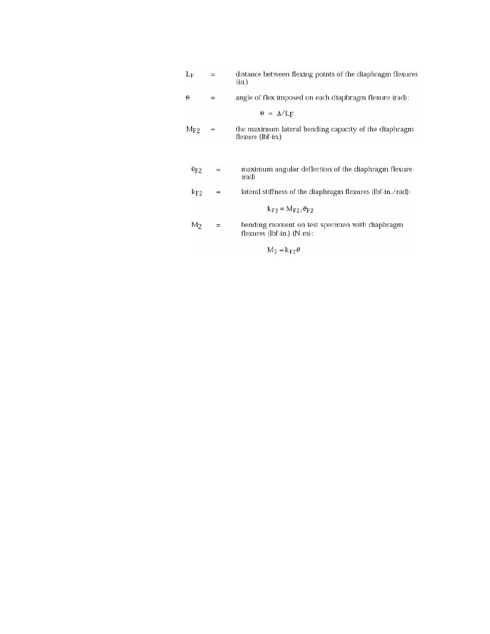
L
F =
13 in. (Distance between flexing points of the diaphragm
flexures) (from Diaphragm Flexure Dimensions and Ratings, rating L)
M
F2
= 400 lbf·in (Maximum lateral bending capacity of the diaphragm
flexure) (from Diaphragm Flexure Dimensions and Ratings, rating M)
θ
F2
= 0.015 rad (Maximum angular deflection of the diaphragm
flexure)
T = 50,000 lbf·in. (Applied torque)