Side load calculations using diaphragm flexures – MTS Series 215 Rotary Actuator User Manual
Page 56
Series 215 Rotary Actuator Product Manual
56
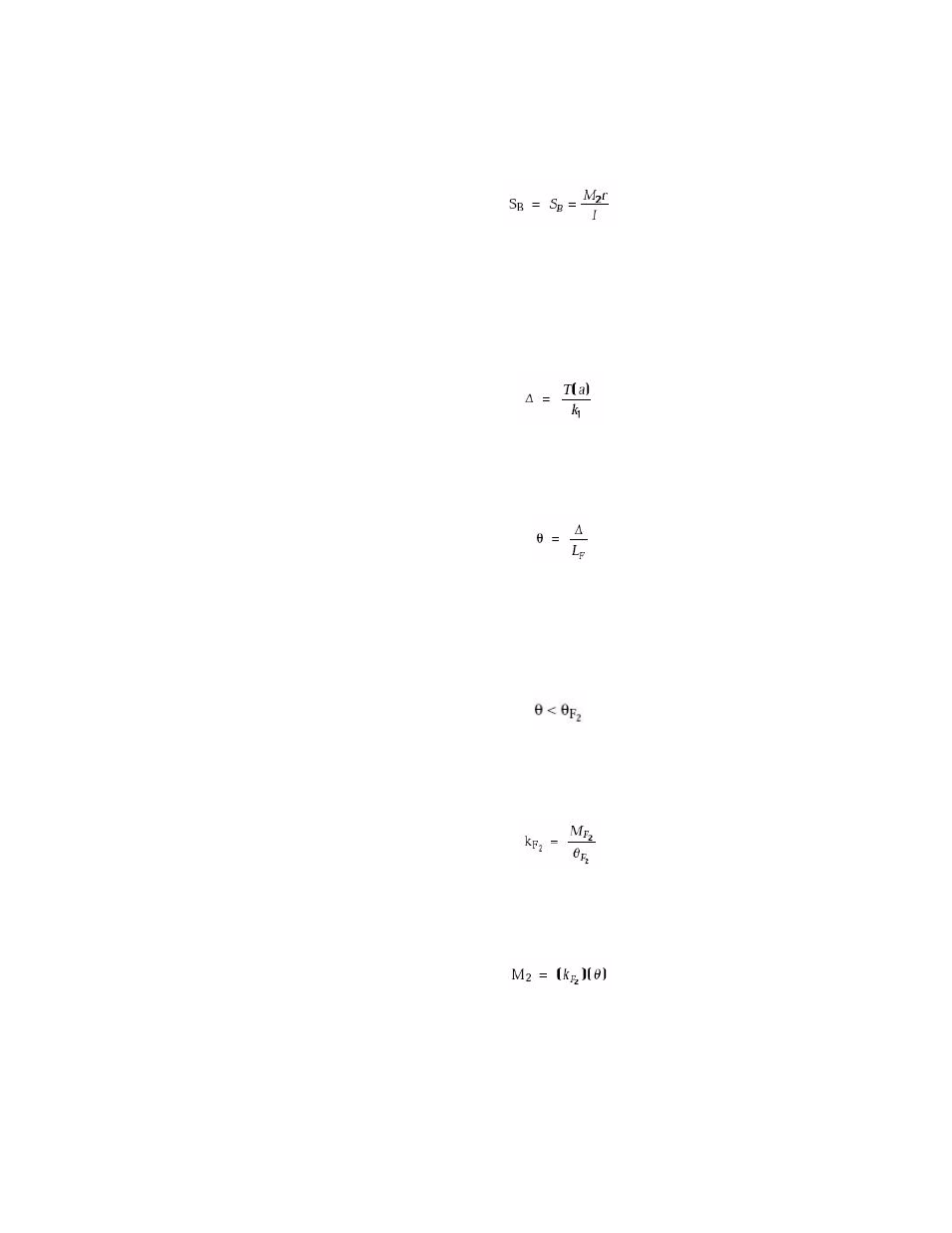
Summary of Side Load Calculations
Operation
7. Calculate the stress (S
B
) induced in the specimen due to base plate twist by
using the following formula:
Side load calculations
using diaphragm
flexures
The following calculations are used when diaphragm flexures are coupled to the
ends of a specimen.
1. Calculate the center line offset (∆) between actuator and reaction bracket
due to base plate twist by using the following formula:
2. Calculate the angle of flex (
θ) imposed on each diaphragm flexure by using
the following formula:
3. Compare the maximum horizontal angular deflection of the diaphragm
flexures in use with the calculated angle of flex imposed on one diaphragm
flexure. This will determine if the flexures are adequate. The relationship
should be:
4. Calculate the lateral stiffness (k
F
2
) of the diaphragm flexures by using the
following formula:
5. Calculate the bending moment (M
2
) that is applied to the test specimen
when equipped with diaphragm flexures.
6. Calculate the stress (S
B
) induced in the specimen due to base plate twist by
using the following formula: