Sample calculation, Calculate side load – MTS Series 215 Rotary Actuator User Manual
Page 43
Test Setup Using No Flexures
Series 215 Rotary Actuator Product Manual
Operation
43
Sample calculation
The previous figure illustrates the forces and measurements pertinent to the
calculations. Refer to the appropriate tables for ratings and dimensions of the
Model 215.45 Rotary Actuator used in the example.
The following procedure uses sample values. When performing the calculations
to determine the anticipated test forces, the values appropriate to your specific
test should be substituted for the sample values. In addition, the example uses
U.S. Customary units of measure.
Calculate the side load (P) and compare P to the actuator's side load rating in the
actuator ratings table. If P exceeds or approaches the side load rating, two
flexures must be used in the test setup.
Also calculate SB, the bending stress on the specimen under test. If SB is above
the determined maximum tolerable value, two flexures must be used in the test
setup.
Example: Suppose a Model 215.45 Rotary Actuator is mounted to a T-slotted
steel reaction base, resulting in the following parameters:
Base: 48 in. x 24 in. x 6 in.
T-slot depth: 2 in.
Height (A from Table 1-4): 7.75 in. (Actuator centerline to base of foot
mounting)
Actuator torque capacity (T): 50,000 lbf-in.
Length of base subjected to twisting (L
1
): 37 in.
Specimen material: Steel (E
S
= 12 x 10
6
, E
T
= 29 x 10
6
)
Specimen length (L
2
): 10 in.
Specimen radius (r): 1 in.
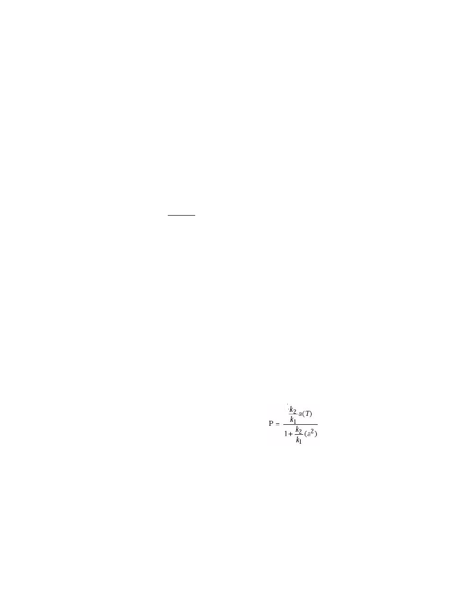
Calculate side load
Calculate the side load (P) imposed on the test specimen and actuator bearing as
a result of base plate twist using the following formula:
A. To calculate P, it is first necessary to calculate k
1
, d,
β, k
2
, I, a, and T as
follows: