Calculate centerline offset – MTS Series 215 Rotary Actuator User Manual
Page 47
Test Setup Using Standard Flexures
Series 215 Rotary Actuator Product Manual
Operation
47
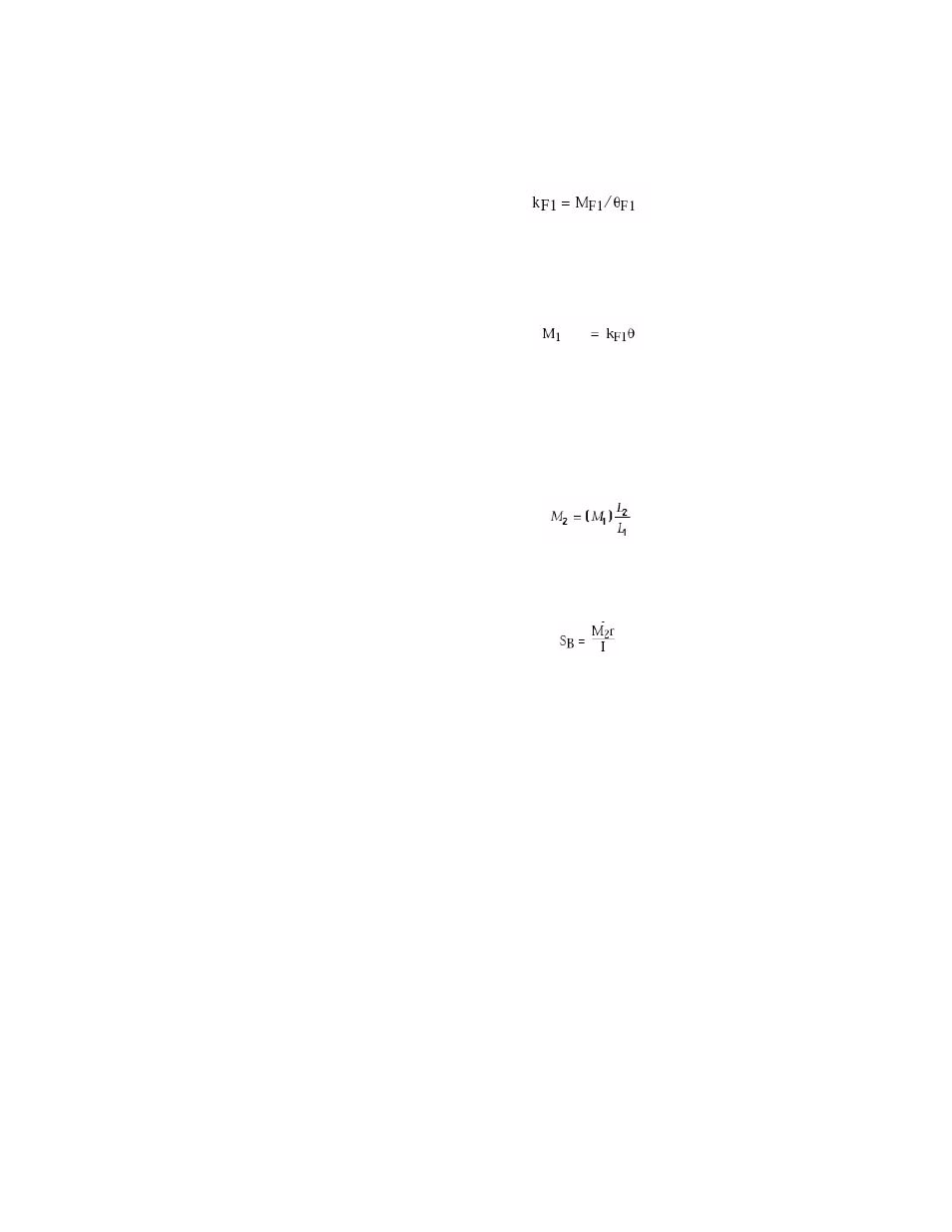
k
F1
= Angular horizontal stiffness of actuator and reaction bracket (N·m/rad)
(lbf·in./rad):
M
1
= Bending moment on actuator and reaction bracket with standard flexures
installed (N·m) (lbf·in.):
M
F1
= Maximum horizontal bending capacity of standard flexures (N·m)
(lbf·in.).
M
2
= Bending moment on specimen with standard flexures installed (lbf·in.)
(N·m):
SB = Bending stress on test specimen due to base plate twisting (N/m
2
) (psi):
The previous figure illustrates the forces and measurements pertinent to the
calculations. Refer to the appropriate tables for ratings and dimensions of the
Model 215.45 Rotary Actuator used in the example.
The following procedure uses sample values. When performing the calculations
to determine the anticipated test forces, the values appropriate to your specific
test should be substituted for the sample values. In addition, the example uses
U.S. Customary units of measure.
Use the following values and formulas to calculate
Δ (centerline offset) and then
θ (angle of flex on flexures). If θ is not greater than θ
F
1, the standard flexures are
adequate.
Also calculate SB, the bending stress on the specimen under test. If SB is above
the determined maximum tolerable value, diaphragm flexures must be used in the
test setup.
Calculate centerline
offset
Calculate the centerline offset (D) between the actuator and reaction bracket
mountings due to base plate twist by using the following formula: