Test setup using no flexures, Side load calculations, Test setup using no flexures 42 – MTS Series 215 Rotary Actuator User Manual
Page 42
Series 215 Rotary Actuator Product Manual
42
Test Setup Using No Flexures
Operation
Test Setup Using No Flexures
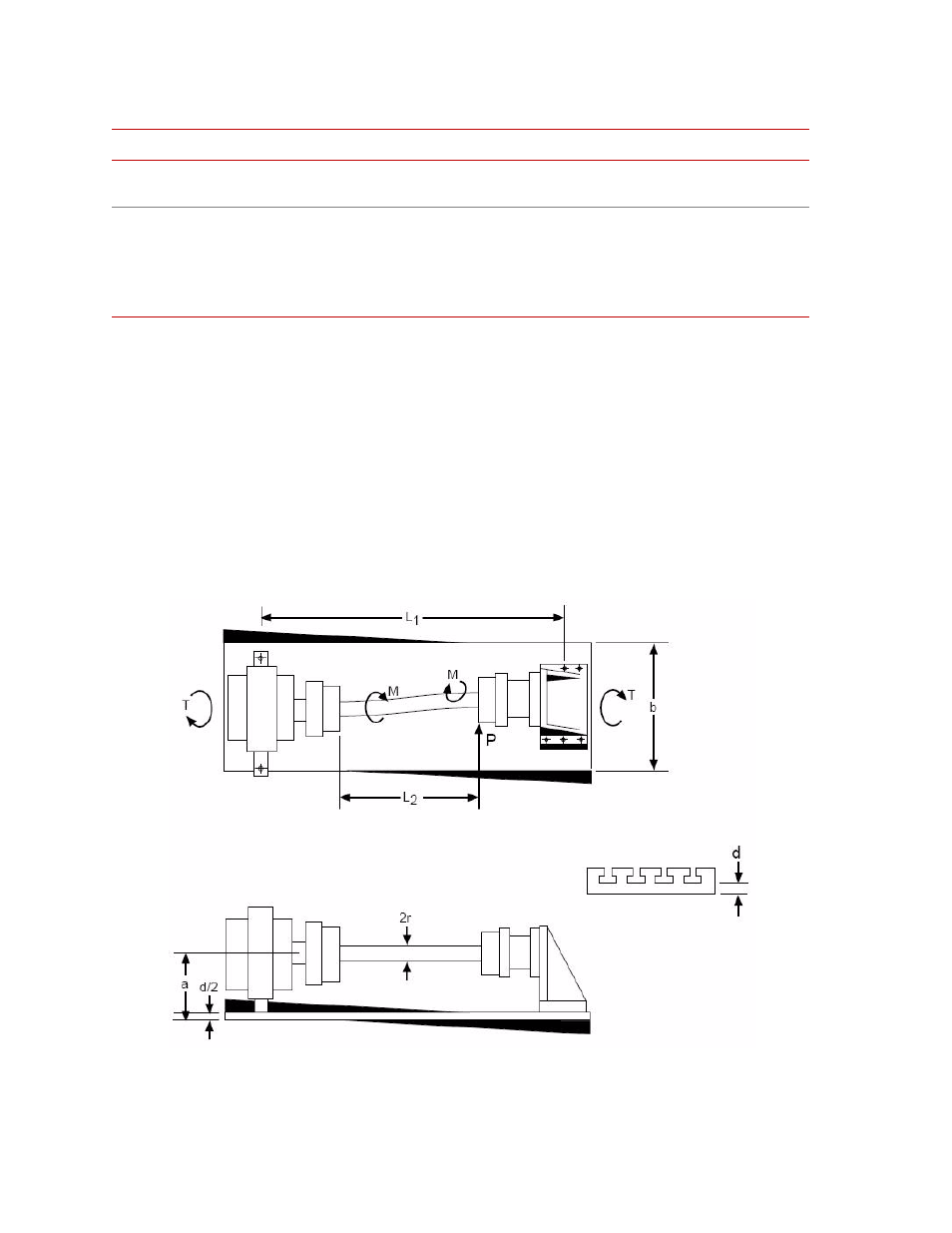
The following figure illustrates an example of a test setup having no flexures. If
diaphragm flexures will not be used in the rotary actuator test system, special
attention should be paid to the side loads that will be imposed on the specimen
and actuator by twisting of the base plate or T-slot table.
Side load calculations
The following side load calculation procedure is used to determine side loads due
to the base plate or T-slot table torsional compliance. When side loads are
unacceptable as determined from these calculations, optional components are
required in the force train to reduce the load imposed on the actuator and torque
sensor.
Loads on an Actuator and Specimen due to base plate twist (excludes thrust loads)
s
Distance between front and rear
bearings (mm) (in.).
θ
F
1
Maximum horizontal angular deflection of
standard flexures (rad).
S
B
Bending stress on test specimen due to
base plate twisting (N/m
2
) (psi).
MrI Without Flexures
M2rI With Flexures
θ
F
2
Maximum angular deflection of diaphragm
flexures (rad).
Mathematical Terms (part 3 of 3)
T
ERM
D
EFINITION
T
ERM
D
EFINITION