Closed-loop rotary actuator systems, Closed-loop rotary actuator systems 15 – MTS Series 215 Rotary Actuator User Manual
Page 15
Closed-Loop Rotary Actuator Systems
Series 215 Rotary Actuator Product Manual
Introduction
15
Closed-Loop Rotary Actuator Systems
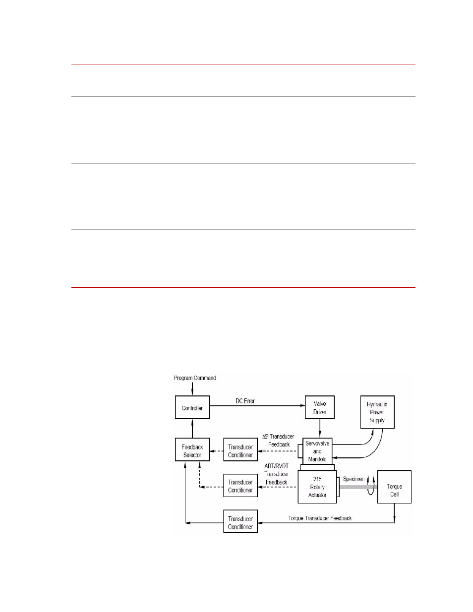
In a closed-loop control system containing a rotary actuator, a command signal
sent to the actuator servovalve is compared to a feedback signal received from an
actuator transducer. The following figure shows a block diagram of the major
components in a typical rotary actuator closed-loop control system.
Block Diagram of a Testing System Using a Rotary Actuator
Torque cell
A torque cell provides a precise electrical feedback signal that is proportional to
the torque applied to the specimen. For more information on MTS torque cells,
refer to the appropriate MTS product specification.
ADT
An angular displacement transducer (ADT) connected to the rear shaft of the
actuator produces a DC electrical signal that is proportional to the angular position
of the actuator. Rotation of the actuator will generate a feedback signal
(0 V DC to ±10 V DC) from the ADT to the transducer conditioner. Rotation is
continuous with no reactive torque induced. The ADT is a precision differential
capacitor coupled to a solid state oscillator, demodulator, and amplifier to yield
DC input - DC output performance.
RVDT
A rotary variable differential transformer (RVDT) attached to the rear shaft of the
actuator provides an AC feedback signal proportional to the angular position of
the actuator. As the actuator rotates, a feedback signal is sent to the transducer
conditioner. An RVDT converts a mechanical angular displacement into an
electrical output by means of an electrical input carrier. It consists of a rotor
assembly to which the mechanical input is applied, and a stator assembly in which
the windings are contained.
Differential pressure
cell
The differential pressure (∆P) cell is a single-unit, dual port, bonded strain gage
pressure sensor. Depending on the specific application, the ∆P cell is used to
stabilize or control actuator force output. The ∆P cell (located beneath the
servovalve) provides a feedback signal to a controller monitoring fluid pressure
within the actuator housing. For more information on MTS ∆P cells, refer to the
appropriate MTS product specification.
Optional Equipment for Series 215 Rotary Actuators (Continued)