Test setup using standard flexures, Test setup using standard flexures 46 – MTS Series 215 Rotary Actuator User Manual
Page 46
Series 215 Rotary Actuator Product Manual
46
Test Setup Using Standard Flexures
Operation
on the test specimen which can invalidate the test results or cause premature
failure of the specimen. To reduce these loads requires the use of flexure options
or a stiffer mounting surface.
Test Setup Using Standard Flexures
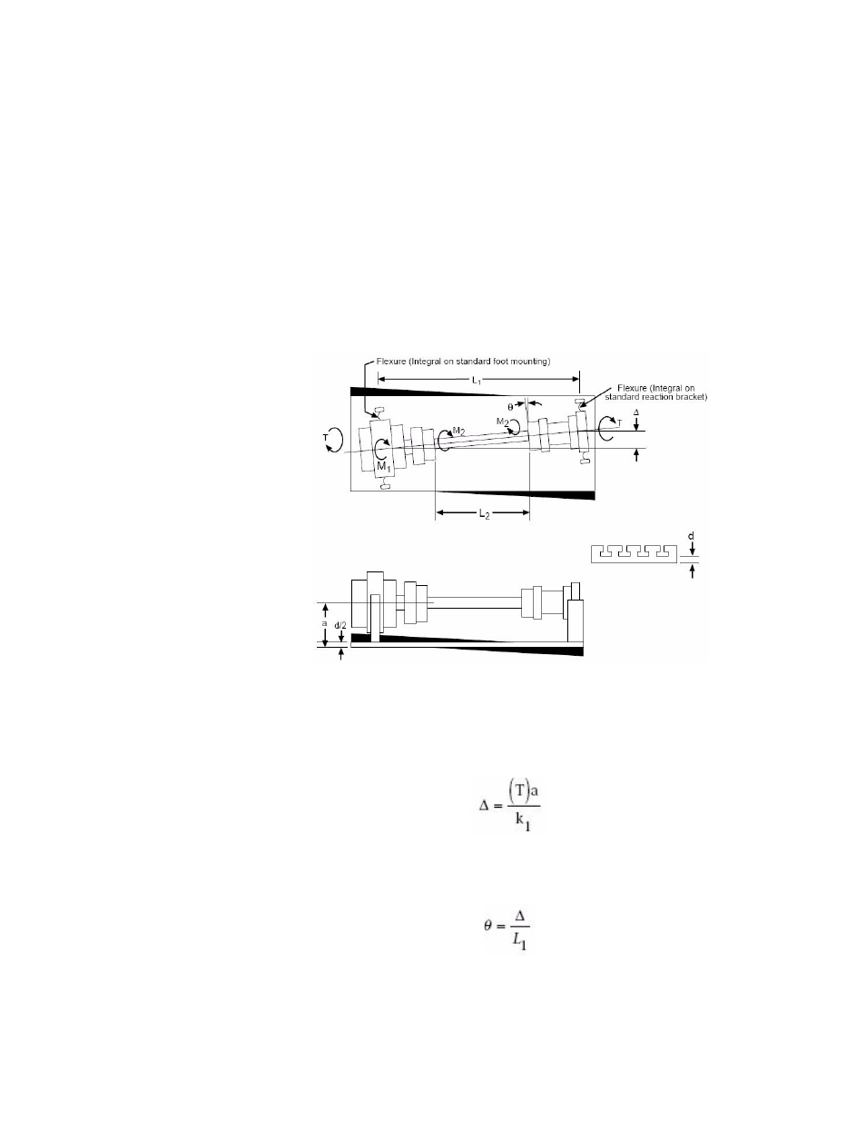
The following figure shows an example of a test setup in which flexures are
integral on both the actuator foot mounting and the reaction bracket. Flexures are
used to reduce excessive side load forces applied to an actuator or specimen.
It is important to determine if standard flexures are adequate for your test setup
or if diaphragm flexures need to be used. This subsection describes calculations
that help make this determination.
Forces Resulting from Base Plate Twisting (Integral Flexures)
∆ = Center line offset between actuator and reaction bracket mountings due to
base plate twisting or T-slot table (in.) (mm):
θ = Angle of flex imposed on actuator and reaction bracket flexures (rad):
θ
F1
= Maximum horizontal angular deflection of standard flexures (rad).