Summary of side load calculations, Side load calculations excluding flexures, Summary of side load calculations 54 – MTS Series 215 Rotary Actuator User Manual
Page 54
Series 215 Rotary Actuator Product Manual
54
Summary of Side Load Calculations
Operation
Summary of Side Load Calculations
This section contains a brief summary of side load calculations made before
beginning a test.
Side load calculations
excluding flexures
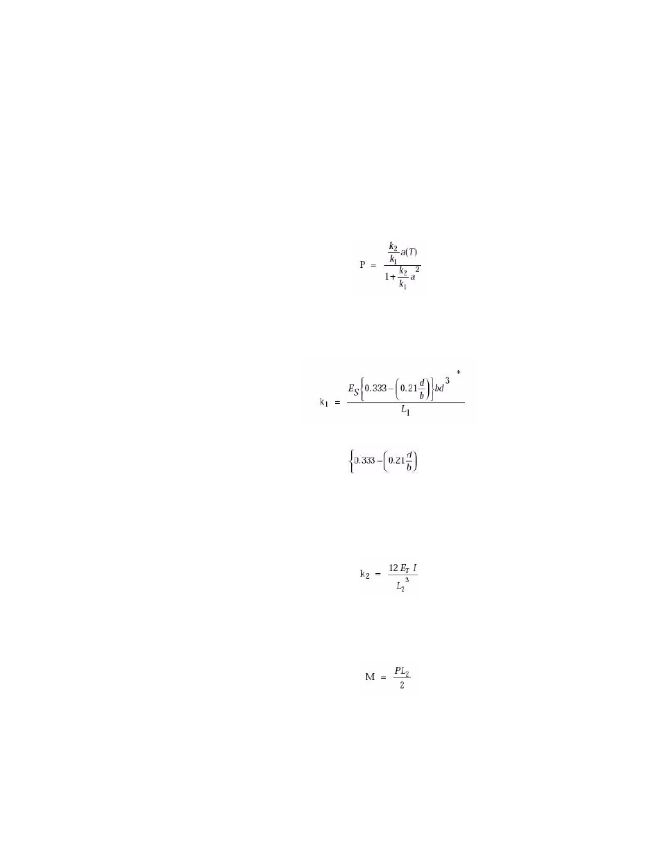
The following formulas are used in preliminary calculations to determine if
forces generated exceed the actuator rating, thus requiring the addition of
flexures.
1. Calculate the side load (P) imposed on the test specimen and actuator
bearing as a result of base plate twist using the following formula:
A. Calculate the value of k
1
, the torsional stiffness of a thin flat plate, by
using the formula:
Note
In the above formula,
is used in place of J (polar
momentary inertia) due to warpage that occurs in thin flat plates under
torque.
B. Calculate the value of k
s
, the lateral stiffness of a solid cylindrical
specimen, by using the formula:
2. Calculate the bending moment (M) on the test specimen by using the
following formula:
3. Calculate the stress (S
B
) induced in the specimen due to base plate twist by
using the following formula: