2111 interbus fieldbus module, 4 installation – Lenze EMF2111IB User Manual
Page 9
Installation
Components of the fieldbus module
5
2111 INTERBUS fieldbus module
5.4
5.4.1
L
5.4-1
EDSIBS-1.0-06/2003
5.4
Installation
5.4.1
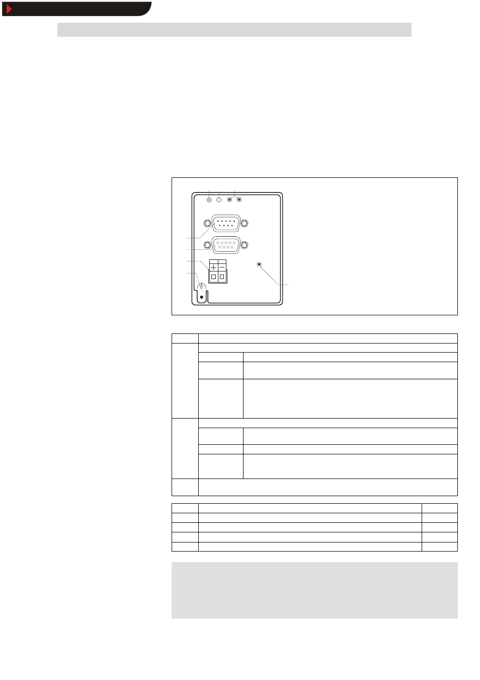
Components of the fieldbus module
INTERBUS S
2111
L
BUS
OUT
IN
24V DC
+
_
DRIVE
01 2
3
4
5
7
6
2111IBU004
Fig. 5.4-1
Components of the fieldbus module
Pos
LED status
Explanation
3
0
Green bus LED (voltage supply)
0
ON
The fieldbus module is supplied with voltage and is connected to the drive controller.
OFF
The fieldbus module is not supplied with voltage. The drive controller or external
voltage supply is switched off.
BLINKING
The fieldbus module is supplied with voltage, but it is not connected to the drive
controller, because
•
the fieldbus module was not plugged on the drive controller correctly
•
the data transfer of/to the drive controller is not possible (e. g. the drive controller
is in the initialisation phase).
1
Yellow bus LED (communication)
1
ON
Fieldbus module is initialised,
inactive INTERBUS communication of the master
OFF
Fieldbus module is not initialised yet
BLINKING
Active INTERBUS communication
•
SLOW (1 Hz): process data and PCP communication.
•
FAST (4 Hz): only process data
2
Red and green drive LED indicate the operating mode of the drive controller 82XX or 93XX (see the
Operating Instructions of the drive controller)
3
INTERBUS input (IN), Sub-D plug connector, 9-pole
^ 5.4-6
4
INTERBUS output (OUT), Sub-D socket connector, 9-pole
^ 5.4-7
5
Plug connector, connection for external voltage supply
^ 5.4-5
6
PE connection
see note
7
Fixing screw
)
)
)
)
Note!
Only for 820X and 821X: If required use an additional PE screen
cable which avoids EMC-related communication interference in
surroundings with interferences.
Show/Hide Bookmarks