2111 interbus fieldbus module, 4 prepare controller for interbus operation – Lenze EMF2111IB User Manual
Page 19
Commissioning
Prepare controller for INTERBUS operation
5
2111 INTERBUS fieldbus module
5.5
5.5.4
L
5.5-3
EDSIBS-1.0-06/2003
5.5.4
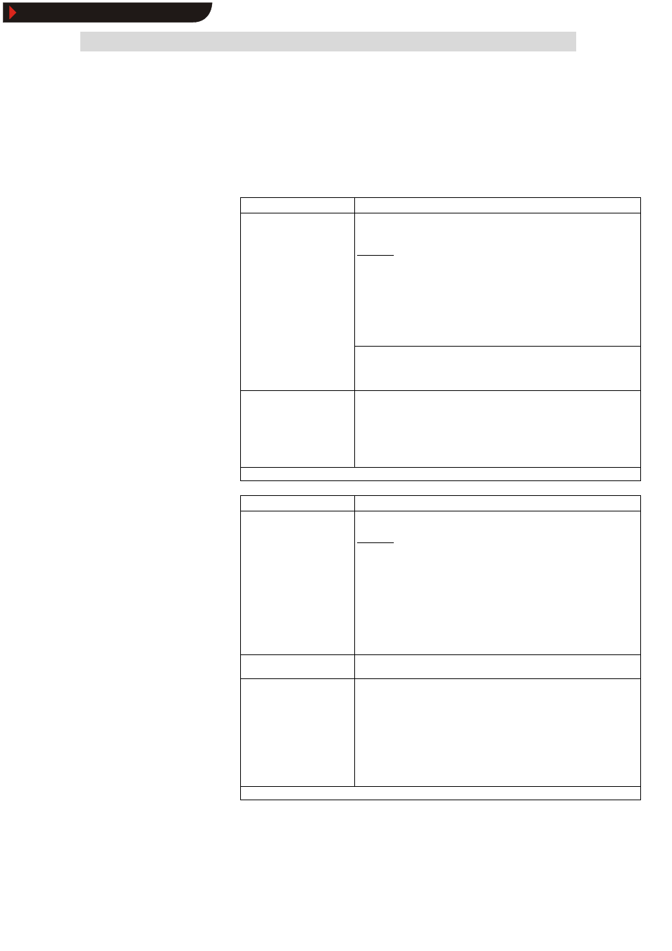
Prepare controller for INTERBUS operation
Preparation
Notes
1. L-C0001 (operating mode):
Change value from “0” to “3”
.
For this use
•
the 8201BB for 82XX and
•
the keypad for 8200 vector
Alternative:
Direct access to the code via INTERBUS.
Example
Set code L-C0001 to “3” (PCP write):
– Index: 5FFE
hex
(= 5FFF
hex
− (L-C0001)
hex
)
– Subindex: 0
– Value: 30000
dec
à
For conversion formula and parameter value range see
^ 5.6-46
8200 vector (up to SW version 1.1)
à
C0410/y (y = 1...16) must be assigned to the AIF control word (AIF-CTRL)
i.e. C0410/1 = 10, C0410/2 = 11 .... C0410/16 = 25 (see Operating
Instructions for 8200 vector).
2. Terminal 28 (controller
enable) must be HIGH during
INTERBUS operation.
Terminal 28 is always
active!
Otherwise, the controller cannot be enabled by the INTERBUS (DRIVECOM
controller status ”OPERATION ENABLED”, see Operating Instructions for the
controller).
821X, 8200vector und 822X
With these controllers the QSP function is always active. If QSP is assigned to an
input terminal (default setting: not assigned), this terminal must be at HIGH level
during INTERBUS operation (see the corresponding Operating Instructions).
The controller is now ready to accept process and parameter data from the INTERBUS.
Preparation
Notes
1. L-C0005: Set “xxx3”.
Use the 9371BB keypad
Alternative:
Direct access to the code via INTERBUS.
For the first commissioning you should select the signal configuration 1013 (speed
control).
Example
Set code L-C0005 to “1013” (PCP write):
– Index: 5FFA
hex
(5FFF
hex
− (L-C0005)
hex
)
– Subindex: 0
– Value: 10130000
dec
à
For conversion formula and parameter value range see
^ 5.6-46
2. L-C0142 (autostart lock):
Set “0”.
Only necessary with DRIVECOM control
3. Terminal 28 (controller
enable) must be HIGH during
INTERBUS operation.
Terminal 28 is always
active!
Otherwise, the controller cannot be enabled by the INTERBUS (DRIVECOM
controller status ”OPERATION ENABLED”, see Operating Instructions for 93XX).
à
With the signal configuration L-C0005=1013, the function QSP (quick stop) and
the CW/CCW changeover are assigned to the digital input terminals E1 and E2
and thus they are always active. For INTERBUS operation E1 must be set to
HIGH level (see Operating Instructions 93XX).
à
With the signal configuration L-C0005=xx13, terminal A1 is switched as
voltage output. Thus, only the following terminals can be connected via cables:
– X5.A1 with X5.28 (ctrl. enable)
– X5.A1 with X5.E1 (CW/QSP)
The controller is now ready to accept process and parameter data from the INTERBUS.
82XX / 8200 vector
93XX controllers
Show/Hide Bookmarks