2111 interbus fieldbus module – Lenze EMF2111IB User Manual
Page 13
Installation
Electrical installation
5
2111 INTERBUS fieldbus module
5.4
5.4.3
L
5.4-5
EDSIBS-1.0-06/2003
If necessary, supply the 2111 fieldbus module with a separate supply voltage
24 V DC via the two-pole plug connector
±10 %.
Plug connector
Name
Explanation
+
Vcc24
External supply 24 V DC ± 10 %, 150 mA
-
GND24
Reference potential for external voltage supply
Use a separate power supply unit in each control cabinet.
Controller
External voltage supply
820X
Always required
821X / 822X / 824X and
93XX
Only necessary if the mains which supply the corresponding controllers is to be switched
off but the communication must not be interrupted.
8200 vector
See information in “internal DC voltage supply”
Electrical connection
Plug connector with threaded terminal end
Possible connections
rigid: 1.5 mm
2
(AWG 16)
flexible:
without wire crimp cap
1.5 mm
2
(AWG 16)
with wire crimp cap, without plastic sleeve
1.5 mm
2
(AWG 16)
with wire crimp cap, with plastic sleeve
1.5 mm
2
(AWG 16)
Tightening torque
0.5 ... 0.6 Nm (4.4 ... 5.3 lb-in)
Bare end
6 mm
)
)
)
)
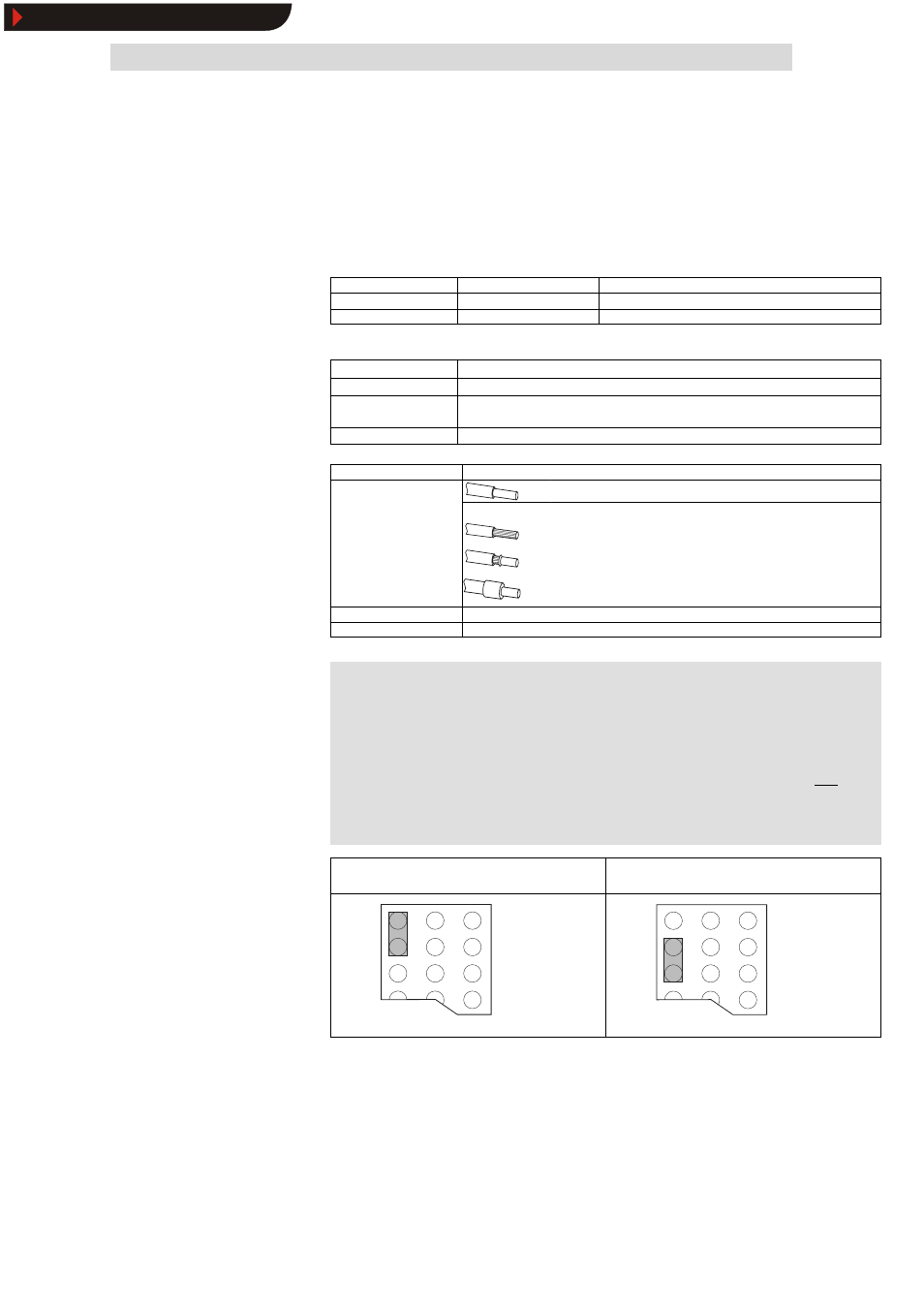
Note!
Basic devices with extended AIF interface opening (8200 vector
front) can be internally supplied. The part of the drawing
highlighted in grey shows the jumper position.
l
In the delivery state of the frequency inverter these are not
internally supplied.
l
For internal voltage supply, put the jumper in the position
indicated below.
Lenze setting
only external voltage supply
Internal voltage supply
External DC voltage supply
6
Connection terminals
7
Internal DC voltage supply
8
Show/Hide Bookmarks