2111 interbus fieldbus module – Lenze EMF2111IB User Manual
Page 41
Data transfer
Process data signals of Lenze controllers
5
2111 INTERBUS fieldbus module
5.6
5.6.2
L
5.6-19
EDSIBS-1.0-06/2003
5.6.2.4
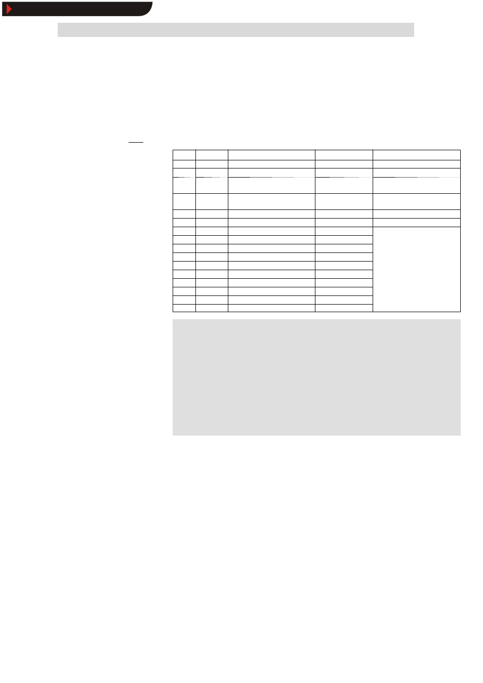
Process data signals for 9300 servo PLC and Drive PLC
The following data can be assigned to the PE data:
Index
Subindex
Name/variable name
Explanation
Lenze setting: Index 6000
hex
6041 0
DRIVECOM status word
PI data word 1
6044 0
DRIVECOM speed
Actual speed [rpm]
PI data word 2
6054 0
DRIVECOM actual percentage
value
Actual speed [%]
5F69 0
Device status word
(AIF1_DctrlStat)
5CA5 1
AIF_nOutW1_a
AIF word 1
5CA5 2
AIF_nOutW2_a
AIF word 2
PI data word 3
5CA5 3
AIF_nOutW3_a
AIF word 3
5CA5 4
AIF2_nOutW1_a
AIF word 4
5CA5 5
AIF2_nOutW2_a
AIF word 5
5CA5 6
AIF2_nOutW3_a
AIF word 6
5CA5 7
AIF2_nOutW4_a
AIF word 7
5CA5 8
AIF3_nOutW1_a
AIF word 8
5CA5 9
AIF3_nOutW2_a
AIF word 9
5CA5 10
AIF3_nOutW3_a
AIF word 10
5CA5 11
AIF3_nOutW4_a
AIF word 11
5CA4 0
AIF1_dnOutD1_p
AIF double word 1
)
)
)
)
Note!
9300 Servo PLC
Please execute the following logic operations in the PLC program
of the controller:
AIF1_wDctrlCtrl
W DCTRL_wAIF1Ctrl
DCTRL_wStat
W AIF1_wDctrlStat
Drive PLC
It is necessary to use the device control for the Drive PLC.
Process data telegram from
drive
Show/Hide Bookmarks