2111 interbus fieldbus module – Lenze EMF2111IB User Manual
Page 37
Data transfer
Process data signals of Lenze controllers
5
2111 INTERBUS fieldbus module
5.6
5.6.2
L
5.6-15
EDSIBS-1.0-06/2003
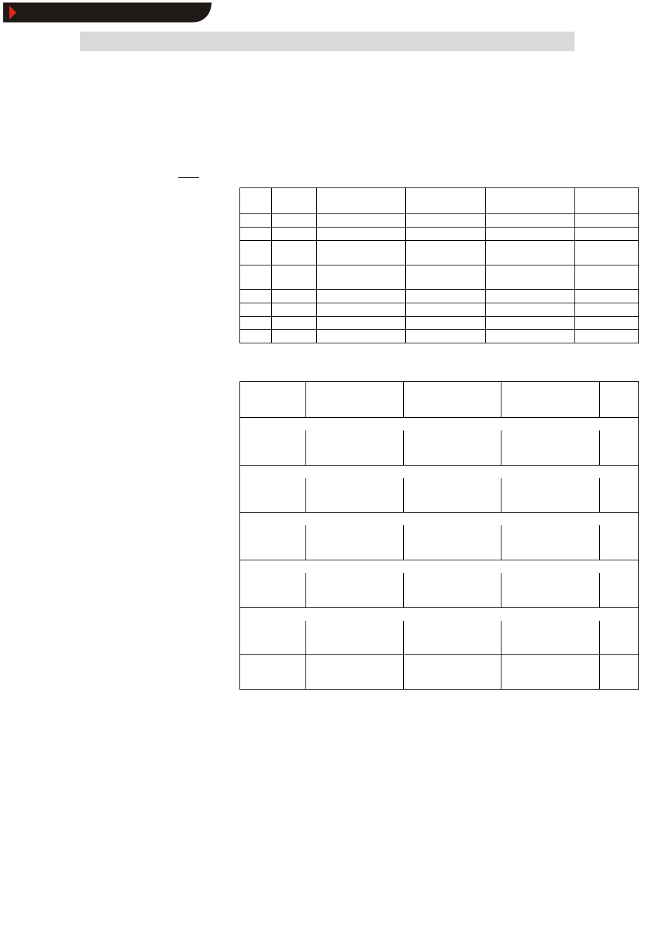
The following parameters can be assigned to the PI-data:
Index
Subindex
Name (same in
IEC1131)
Explanation
Lenze setting:
Index 6000
hex
see
6041
0
DRIVECOM status word
PI data word 1
^ 5.6-38
6044
0
DRIVECOM speed
Actual speed [rpm]
PI data word 2
^ 5.6-41
6054
0
DRIVECOM actual
percentage value
Actual speed [%]
^ 5.6-42
5F69
0
Device status word
(AIF1_Stat)
Table below
5CA5
1
AIF1-OUT.W1
AIF word 1
5CA5
2
AIF1-OUT.W2
AIF word 2
PI data word 3
5CA5
3
AIF1-OUT.W3
AIF word 3
5CA4
0
AIF1-OUT.D1
AIF double word
The assignment of AIF-OUT depends on the signal configuration selected under
L-C0005:
Signal
configuration
(L-C0005)
AIF-OUT.W1
AIF-OUT.W2
AIF-OUT.W3
AIF-
OUT.D1
Speed control
1003
1013
1113
MCTRL-NACT
Actual speed
100%=16383
MCTRL-MSET2
Torque display
100%=16383
MCTRL-NSET2
Speed controller input
100%=16383
not
assigned
Torque control
4003
4013
4113
MCTRL-MSET2
Torque display
100%=16383
MCTRL-NACT
Act. speed in %
100%=16383
MCTRL-NSET2
Speed controller input
100%=16383
not
assigned
DF master
5003
5013
5113
MCTRL-NACT
Actual speed
100%=16383
MCTRL-MSET2
Torque display
100%=16383
MCTRL-NSET2
Speed controller input
100%=16383
not
assigned
DF-slave bus
6003
6013
6113
MCTRL-NACT
Actual speed
100%=16383
MCTRL-PHI-ACT
Actual phase
MCTRL-MSET2
Torque setpoint in %
100%=16383
not
assigned
DF-slave cascade
7003
7013
7113
MCTRL-NACT
Actual speed
100%=16383
MCTRL-PHI-ACT
Actual phase
MCTRL-MSET2
Torque setpoint in %
100%=16383
not
assigned
Not equal to xxx3
(except self
configurations)
MCTRL-NACT
Actual speed
100%=16383
MCTRL-MSET2
Torque display
100%=16383
MCTRL-PHI-ACT
Actual phase
not
assigned
For detailed description of the 93XX signal configuration see the Operating
Instructions for 93XX (only the main configurations: 1000, 4000, 5000, etc.) or the
Manual 93XX.
In the controller, other signals can be assigned to AIF-OUT.W1 to AIF-OUT.W3.
For this, the function-block configuration - described in the Manual 93XX - is used.
The function block AIF-OUT determines the output data of the controller as data
interface for the 2133 fieldbus module.
For more detailed information about the function block AIF-OUT, see the Manual
93XX.
Process data telegram from
drive
Show/Hide Bookmarks