Electrical, Electrical schematic, Item part no. qty. description – Kinze Grain Carts Rev. 4/14 User Manual
Page 142
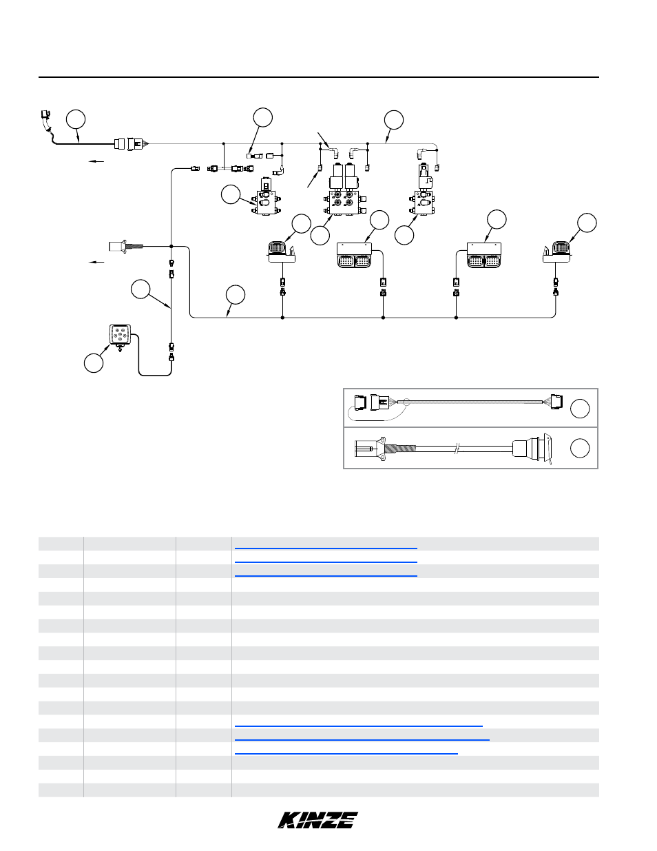
Electrical Schematic
A
B
B
A
B
A
B
A
A
B
A
B
C
A
B
C
A
B
A
A
C
A
B
C
A
B
A
B
B
A
B
A
B
A
Spout Up
Spout Down
Flow Gate Open
Pivot Down
Flow Gate Close
Pivot Up
Auger
Relay
L.H. Flasher
L.H. Tail Light
R.H. Tail Light
R.H. Flasher
See Note
To Tractor
To Tractor
Work Light
B
B
NOTE: Item 4 is routed through the R.H. side of the cart
frame, it exits out the right rear and travels up along
side the rear most side stake. It then wraps around the
rear of the cart to the lights.
6
3
1
2
3
4
7
5
14
15
16
8
17
(IP1385)
ITEM
PART NO.
QTY.
DESCRIPTION
1
---
1
See “Safety/Warning Lights” on page P141
2
---
1
See “Safety/Warning Lights” on page P141
3
---
2
See “Safety/Warning Lights” on page P141
4
GA16931
1
Cart Lighting Cable
5
GA16940
1
Latching Relay
6
GA16695
1
Handheld Control
7
GA16353
1
Cart Control Cable
8
GA15472
1
Work Light
9
G11196
1
Spring Pin, ½" x 4
10
GD16565
1
Seal
11
GB0382
1
Dust Cap
12
G10043
6
Hex Head Cap Screw, 5/16"-18 x ¾"
13
G10625
10
Flange Nut, ¾"-16
14
---
1
See “Floor Auger Manifold Block Assembly” on page P137
15
---
1
See “Auger Rotate Manifold Block Assembly” on page P138
16
---
1
See “Spout Manifold Block Assembly” on page P136
17
GA20045
1
Work Light Cable
18
GA16354
-
Control Cable Extension, 15'
19
GA18949
-
Extension Harness
18
19
TM
M0238-02
Grain Cart
P139
Rev. 4/14