10 appendix, Binary inputs measuring circuit monitoring – JUMO 701550 di 308 - Digital Indicator Operating Manual User Manual
Page 68
10 Appendix
68
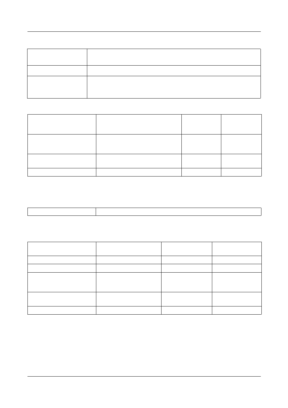
RTD temperature probe input (continued)
Standard signals input
3
The accuracy refers to the max. measurement range span. The linearization accuracy is
reduced with short spans.
Binary inputs
Measuring circuit monitoring
In the event of a fault, the outputs change to defined statuses (configurable).
Sensor lead
resistance
max. 30
Ω
per lead for 3-wire/4-wire circuit
Measuring current
approx. 250µA
Lead compensation
Not required for 3-wire and 4-wire circuit. For a 2-wire circuit, the
lead resistance can be compensated in the software by correcting
the actual value.
Designation
Measuring range
Measuring
accuracy
3
Ambient
temperature
error
Voltage
0(2)—10V
0—1V
Input resistance R
IN
> 100k
Ω
≤
0.05%
≤
0.05%
100ppm/K
100ppm/K
Current
0(4)—20mA
Voltage drop
≤
1.5V
≤
0.05%
100ppm/K
Resistance transmitter
min. 100
Ω
, max. 4k
Ω
±
4
Ω
100ppm/K
Floating contacts
open = inactive; short-circuited to GND = active
Sensor
Measuring overrange /
underrange
Probe or lead
short-circuit
Probe or lead
break
Thermocouple
•
-
•
RTD temperature probe
•
•
•
Voltage 2—10V
0—10V
0—1V
•
•
•
•
-
-
•
-
-
Current 4—20mA
0—20mA
•
•
•
-
•
-
Resistance transmitter
-
-
•
• = detected - = not detected
- 7050xx mTRON T - System description (10 pages)
- 705040 mTRON T - Router Module Operating Manual (74 pages)
- 705040 mTRON T - Router Module Installation Instructions (34 pages)
- 705030 mTRON T - Digital Input/Output Module Data Sheet (7 pages)
- 705030 mTRON T - Digital Input/Output Module Operating Manual (50 pages)
- 705021 mTRON T - Analog Input Module, 8-Ch. Data Sheet (8 pages)
- 705021 mTRON T - Analog Input Module, 8-Ch. Operating Manual (56 pages)
- 705020 mTRON T - Analog Input Module, 4-Ch. Data Sheet (10 pages)
- 705020 mTRON T - Analog Input Module, 4-Ch. Operating Manual (70 pages)
- 705015 mTRON T - Relay Module 4-Ch. Data Sheet (5 pages)
- 705015 mTRON T - Relay Module 4-Ch. Operating Manual (44 pages)
- 705010 mTRON T - Multichannel Controller Module Data Sheet (15 pages)
- 705010 mTRON T - Multichannel Controller Module Operating Manual (148 pages)
- 705001 mTRON T - Central Processing Unit Data Sheet (10 pages)
- 705001 mTRON T - Central Processing Unit Operating Manual (152 pages)
- 705060 mTRON T - Multifunction Panel 840 Data Sheet (13 pages)
- 705060 mTRON T - Multifunction Panel 840 Operating Manual (272 pages)
- 709062 TYA 202 - Three-Phase Power Controller Data Sheet (17 pages)
- 709062 TYA 202 - Three-Phase Power Controller Operating Manual (112 pages)
- 709061 TYA 201 - Single-Phase Power Controller Data Sheet (21 pages)
- 709061 TYA 201 - Single-Phase Power Controller Operating Manual (112 pages)
- 709050 IPC IGBT Power Converter Data Sheet (12 pages)
- 709050 IPC IGBT Power Converter IPC 200A Operating Manual (52 pages)
- 709050 IPC IGBT Power Converter IPC 70/100A Operating Manual (52 pages)
- 709050 IPC IGBT Power Converter IPC 70A Operating Manual (48 pages)
- 709040 TYA-110 thyristor power unit Data Sheet (12 pages)
- 709040 TYA-110 thyristor power unit Operating Manual (56 pages)
- 709020 TYA-432 thyristor power switch Data Sheet (5 pages)
- 709010 TYA-432 thyristor power switch Data Sheet (3 pages)
- 706585 LOGOSCREEN fd Data Sheet (21 pages)
- 706585 LOGOSCREEN fd Operating Instructions (108 pages)
- 706585 LOGOSCREEN fd Operating Manual (228 pages)
- 706585 LOGOSCREEN fd Recorder with diecast zinc front Installation Instructions (40 pages)
- 706585 LOGOSCREEN fd Recorder with stainless steel front Installation Instructions (52 pages)
- 706581 LOGOSCREEN nt Data Sheet (18 pages)
- 706581 LOGOSCREEN nt Operating Instructions (108 pages)
- 706581 LOGOSCREEN nt Operating Manual (224 pages)
- 706581 LOGOSCREEN nt Paperless Recorder with TFT display, CompactFlash Installation Instructions (36 pages)
- 706581 LOGOSCREEN nt stainless steel front Installation Instructions (48 pages)
- 706560 LOGOSCREEN es Data Sheet (12 pages)
- 706560 LOGOSCREEN es Operating Instructions (64 pages)
- 706560 LOGOSCREEN es Operating Manual (128 pages)
- 706560 LOGOSCREEN es Installation Instructions (32 pages)
- 706510 LOGOSCREEN 500 cf Data Sheet (10 pages)
- 706510 LOGOSCREEN 500 cf Operating Manual (140 pages)