4 electrical connection – JUMO 701550 di 308 - Digital Indicator Operating Manual User Manual
Page 22
4 Electrical connection
22
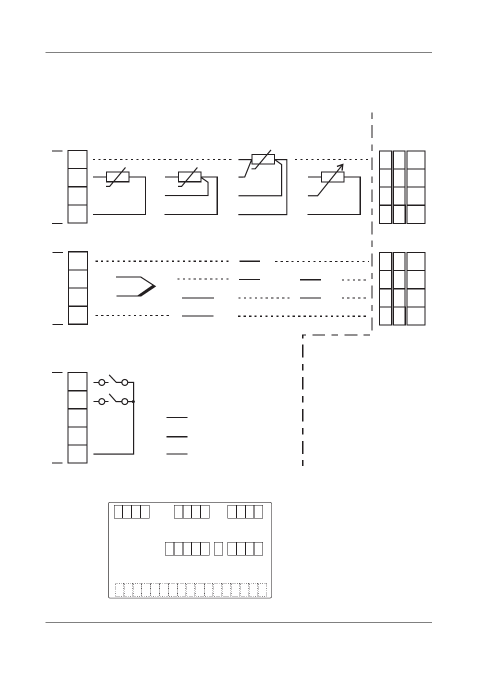
Assignment of terminal strip 2:
Analog input 1, binary inputs 1+2, and binary outputs 3+4
Position of terminal strip 1 and 2 (on the back of the instrument):
1
2
4
3
6
7
8
?
?
E
S
A
RTD temp.
probe
RTD temp.
probe
RTD temp.
probe
Resistance
transmitter
Binary input
1+2
1
2
GND
Binary output
3+4
(logic 12V)
3 (+)
4 (+)
GND (-)
Analog
input 1
Binary
9
10
?
1
2
4
3
Analog
input 1
-
+
-
+
I
x
I
x - /
~
~
U
x
-
+
U
x
-
+
Thermo-
couple
Current
Voltage
0(2)—10V
Voltage
0—1V
5
6
8
7
9
10
12
11
Terminal
strip 1*
* Assignment of
terminal strip 1
for analog input 2
(see also next page)
1
2
4
3
5
6
8
7
9
10
12
11
1
2
4
3
Terminal strip 2
1
2
3
4
1
2
3
4
5
6
7
8
6
7
8
9
10
9
10
11
12
4
L1(L+)
5
6
8
9
11
12
13
15
16
17
N(L+)
Option 1
Option 2
Option 3
Terminal strip 1
Terminal strip 2
Terminal strip 3
See also other documents in the category JUMO Equipment:
- 7050xx mTRON T - System description (10 pages)
- 705040 mTRON T - Router Module Operating Manual (74 pages)
- 705040 mTRON T - Router Module Installation Instructions (34 pages)
- 705030 mTRON T - Digital Input/Output Module Data Sheet (7 pages)
- 705030 mTRON T - Digital Input/Output Module Operating Manual (50 pages)
- 705021 mTRON T - Analog Input Module, 8-Ch. Data Sheet (8 pages)
- 705021 mTRON T - Analog Input Module, 8-Ch. Operating Manual (56 pages)
- 705020 mTRON T - Analog Input Module, 4-Ch. Data Sheet (10 pages)
- 705020 mTRON T - Analog Input Module, 4-Ch. Operating Manual (70 pages)
- 705015 mTRON T - Relay Module 4-Ch. Data Sheet (5 pages)
- 705015 mTRON T - Relay Module 4-Ch. Operating Manual (44 pages)
- 705010 mTRON T - Multichannel Controller Module Data Sheet (15 pages)
- 705010 mTRON T - Multichannel Controller Module Operating Manual (148 pages)
- 705001 mTRON T - Central Processing Unit Data Sheet (10 pages)
- 705001 mTRON T - Central Processing Unit Operating Manual (152 pages)
- 705060 mTRON T - Multifunction Panel 840 Data Sheet (13 pages)
- 705060 mTRON T - Multifunction Panel 840 Operating Manual (272 pages)
- 709062 TYA 202 - Three-Phase Power Controller Data Sheet (17 pages)
- 709062 TYA 202 - Three-Phase Power Controller Operating Manual (112 pages)
- 709061 TYA 201 - Single-Phase Power Controller Data Sheet (21 pages)
- 709061 TYA 201 - Single-Phase Power Controller Operating Manual (112 pages)
- 709050 IPC IGBT Power Converter Data Sheet (12 pages)
- 709050 IPC IGBT Power Converter IPC 200A Operating Manual (52 pages)
- 709050 IPC IGBT Power Converter IPC 70/100A Operating Manual (52 pages)
- 709050 IPC IGBT Power Converter IPC 70A Operating Manual (48 pages)
- 709040 TYA-110 thyristor power unit Data Sheet (12 pages)
- 709040 TYA-110 thyristor power unit Operating Manual (56 pages)
- 709020 TYA-432 thyristor power switch Data Sheet (5 pages)
- 709010 TYA-432 thyristor power switch Data Sheet (3 pages)
- 706585 LOGOSCREEN fd Data Sheet (21 pages)
- 706585 LOGOSCREEN fd Operating Instructions (108 pages)
- 706585 LOGOSCREEN fd Operating Manual (228 pages)
- 706585 LOGOSCREEN fd Recorder with diecast zinc front Installation Instructions (40 pages)
- 706585 LOGOSCREEN fd Recorder with stainless steel front Installation Instructions (52 pages)
- 706581 LOGOSCREEN nt Data Sheet (18 pages)
- 706581 LOGOSCREEN nt Operating Instructions (108 pages)
- 706581 LOGOSCREEN nt Operating Manual (224 pages)
- 706581 LOGOSCREEN nt Paperless Recorder with TFT display, CompactFlash Installation Instructions (36 pages)
- 706581 LOGOSCREEN nt stainless steel front Installation Instructions (48 pages)
- 706560 LOGOSCREEN es Data Sheet (12 pages)
- 706560 LOGOSCREEN es Operating Instructions (64 pages)
- 706560 LOGOSCREEN es Operating Manual (128 pages)
- 706560 LOGOSCREEN es Installation Instructions (32 pages)
- 706510 LOGOSCREEN 500 cf Data Sheet (10 pages)
- 706510 LOGOSCREEN 500 cf Operating Manual (140 pages)