2 monitor crystals, Xtm/2 operating manual – INFICON XTM/2 Thin Film Deposition Monitor User Manual
Page 96
5 - 6
IP
N 07
4-
18
6S
XTM/2 Operating Manual
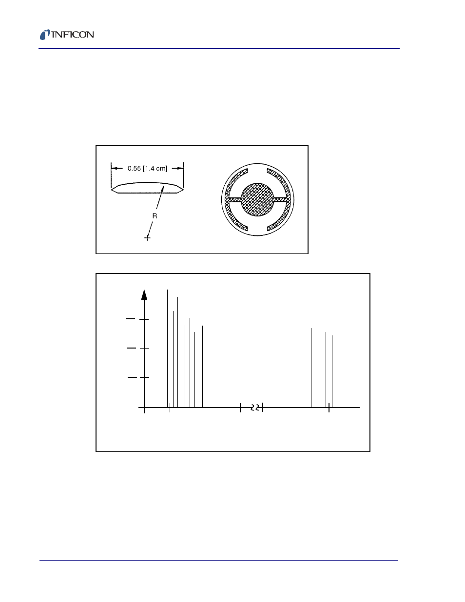
5.5.2 Monitor Crystals
No matter how sophisticated the electronics surrounding it, the essential device
of the deposition monitor is the quartz crystal. The quartz resonator shown in
Figure 5-1
has a frequency response spectrum that is schematically shown in
Figure 5-2
. The ordinate represents the magnitude of response, or current flow
of the crystal, at the specified frequency.
Figure 5-1 Quartz Resonator
Figure 5-2 Frequency Response Spectrum
The lowest frequency response is primarily a “thickness shear” mode that is
called the fundamental. The characteristic movement of the thickness shear
mode is for displacement to take place parallel to the major monitor crystal
faces. In other words, the faces are displacement antinodes as shown in
Figure
5-3
. The responses located slightly higher in frequency are called anharmonics;
they are a combination of the thickness shear and thickness twist modes. The
5.
98
1 MH
z 1
5
o
h
m
6.
15
3 MH
z 5
0
o
h
m
6.
19
4 MH
z 4
0
o
h
m
6.
33
3 MH
z 1
4
2
oh
m
6.
33
7 MH
z 1
0
5
oh
m
6.
34
8 MH
z 3
2
2
oh
m
6.
41
9 MH
z 3
5
0
oh
m
17
.7
92
MH
z 27
8 o
h
m
17
.9
57
MH
z 31
1 o
h
m
18
.1
33
MH
z 35
0 o
h
m
Log
of relative intensity (Admitt
a
nce)
Frequency (in MHz)
1
10
1
100
1
1000
6
7
17
18