Enerpac ATM-9 User Manual
Page 7
77
13.0 TROUBLESHOOTING
Problem 1:
The hydraulic cylinder is sliding on the circumference of
the opposite flange as the ATM-9 is aligning the joint.
Cause:
Grit or dirt on wing, rollers or bearings, wing is at full
extension.
Solution:
A. Ensure the rollers are rotating freely and that there is
no restriction to the rollers on the wing surfaces such
as dirt or grit.
B. Check that the wing is not at full extension when
aligning the joint.
C. Ensure that there is enough extension left to allow
the ATM-9 to expand as the joint is aligned.
Problem 2:
The ATM-9 is attached and appears to be functioning
properly, but the joint will not align.
Cause:
A. There may be air in the hydraulic system restricting
the force on the flanges.
B. There may be something restricting the joint at a
point close to the flanges. The joint may require more
than 9 ton [90 kN] pressure to align.
Solution:
A. See air lock removal instructions in section 14.
B. Check the area around the joint to establish if there
is an obstruction to the joint.
C. If the joint requires more force than that of the 9 ton
[90 kN] capacity of the tool, then another method to
align the joint should be adopted.
14.0 AIR LOCK REMOVAL
Remove air as described in the following steps:
1. Remove the air vent cap on top of the hydraulic
pump and check hydraulic oil level to ensure there is
enough oil to advance the cylinder.
2. Replace air vent cap, but do not tighten the cap.
The cap must remain loose (in the “vent” position) to
allow air to enter and leave the pump during use. The
cap should only be tightened fully when the tool is to
be returned to the carrying case after use.
3. With the air vent cap loose, connect the pump to
the tool with the hydraulic hose supplied within the
carrying case.
4. Stand the tool on a level surface, hold the hydraulic
pump above the tool, close the release valve on the
pump, and prime the pump to advance the hydraulic
cylinder until the cylinder is fully advanced and a
small pressure is achieved.
5. With the hydraulic pump held above the tool, open
the release valve allowing the cylinder to retract fully
back. While the cylinder is retracting any air that is
within the system will be forced up to the pump and
vented out through the air vent cap.
6. Repeat the above procedure three or four times to
ensure that all air is removed and the tool will reach
full working pressure.
15.0 MINIMUM / MAXIMUM EXTENSION
Refer to section 18.0, Weights and Dimensions, for
minimum and maximum extension information.
16.0 APPLICATION RANGE
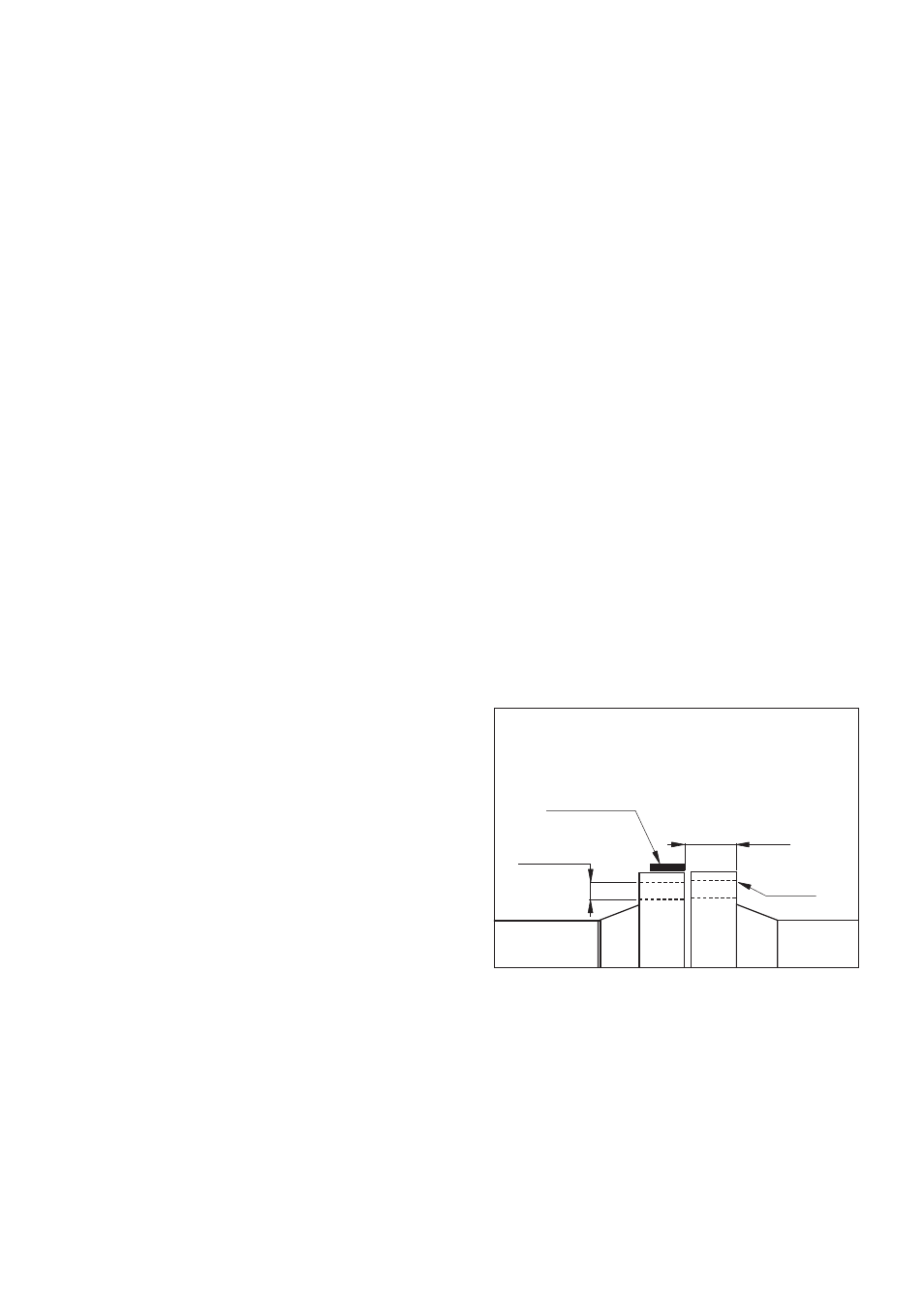
Two basic dimensions, A and B, will determine if the
ATM-9 can be used to align the joint. If the flange joint
to be aligned is between 3.66 inch [93 mm] and 9 inch
[228 mm] as illustrated by (A), has a bolt hole size of
1.24 inch [31,5 mm] or greater (B), then the ATM-9 can
be attached and alignment achieved (see fig. 14).
See charts in section 17: by flange type, class and
diameter.
Fig. 14 – Min. and max. flange sizes (visual)
Min. bolt hole size
1.24 inch [31,5 mm]
Min. distance 3.66 inch [93 mm]
Max. distance 9 inch [228 mm]
Hook into this
bolt hole
Saddle of hydraulic
cylinder must rest fully on
the circumference of the
flange to be pushed.
A
B