Despatch MIC1462 Controller Manual User Manual
Page 80
76
3. Enter Calibration Mode. The lower main display will then show Input Type Number,
in the form:
iP_I
and the message display will show:
Calib
Using the UP/DOWN keys, change the input type number as required (see Table 12-1).
NOTE: If required, only one input type may be calibrated. Exception: If it is required to
calibrate the thermocouple input (Input Type 5), it is necessary first to calibrate the DC
0 - 50 mV input (Input Type 1).
4. Press the PROF key to change the lower main display to show: _ _ _ _
After a few seconds, the lower main display will either (a) return to the initial Input Type
Number display if calibration was successful, or (b) display:
FAIL
In the latter case, the link jumpers and wiring should be checked.
5. To calibrate all inputs, repeat Steps 1 to 4 for each of the other input types (see
Table 12-1) until all five input types have been successfully calibrated.
The universal input calibration procedure is now complete.
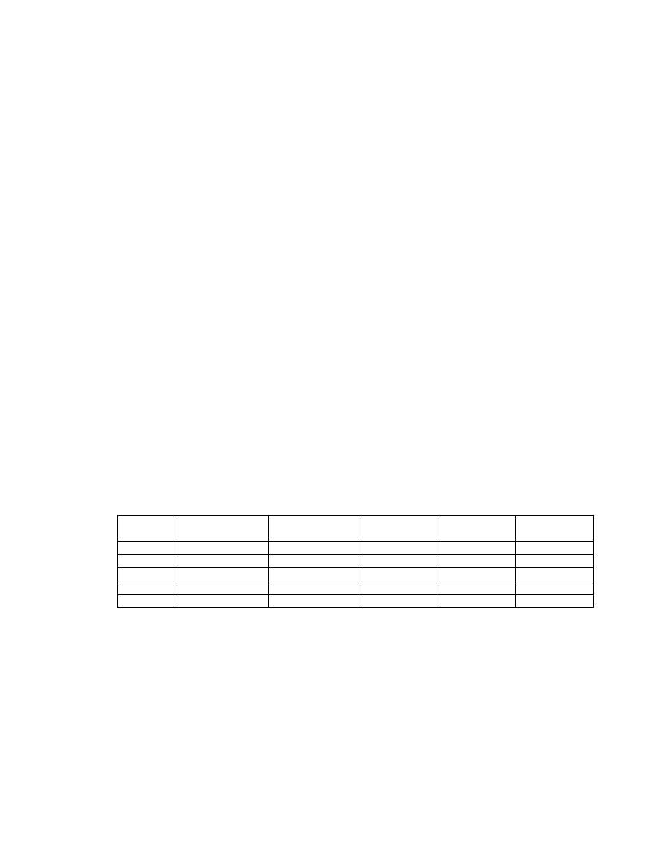
Table 12-1 Universal Input Type Selection
Input
Type No.
Input Type
Calibration Input
Link Jumper
1
Link Jumper
2
Link Jumper
3
1
0 - 50 mVDC
50 mVDC
Parked
Parked
Parked
2
0 - 10 VDC
10 VDC
Fitted
Parked
Parked
3
0 - 20 mADC
20 mADC
Parked
Fitted
Parked
4
3-wire RTD
200 ohm
Parked
Parked
Parked
5
Thermocouple
0° C (“K“-type)
Parked
Parked
Fitt ed