Despatch MIC1462 Controller Manual User Manual
Page 19
15
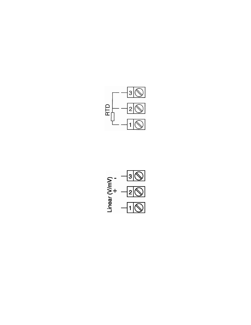
FIGURE 2-9
RTD Input
Make RTD connections as illustrated below. For a three wire RTD, connect the
resistive leg of the RTD to terminal 1 and the common legs to terminals 2 and 3. For a
two wire RTD, connect one leg to terminal 2 and the other leg to terminal 3 as shown
below. A jumper wire supplied by the customer must be installed between terminals 2
and 3. Input conditioning jumper must be positioned correctly (see Appendix B) and
Hardware Definition Code must be correct (see Section 10).
FIGURE 2-10
Volt, mV Input
Make volt and millivolt connections as shown below. Terminal 2 is positive and terminal
3 is negative. Input conditioning jumper must be positioned correctly (see Appendix B)
and Hardware Definition Code must be correct (see Section 10).