Despatch MIC1462 Controller Manual User Manual
Page 20
16
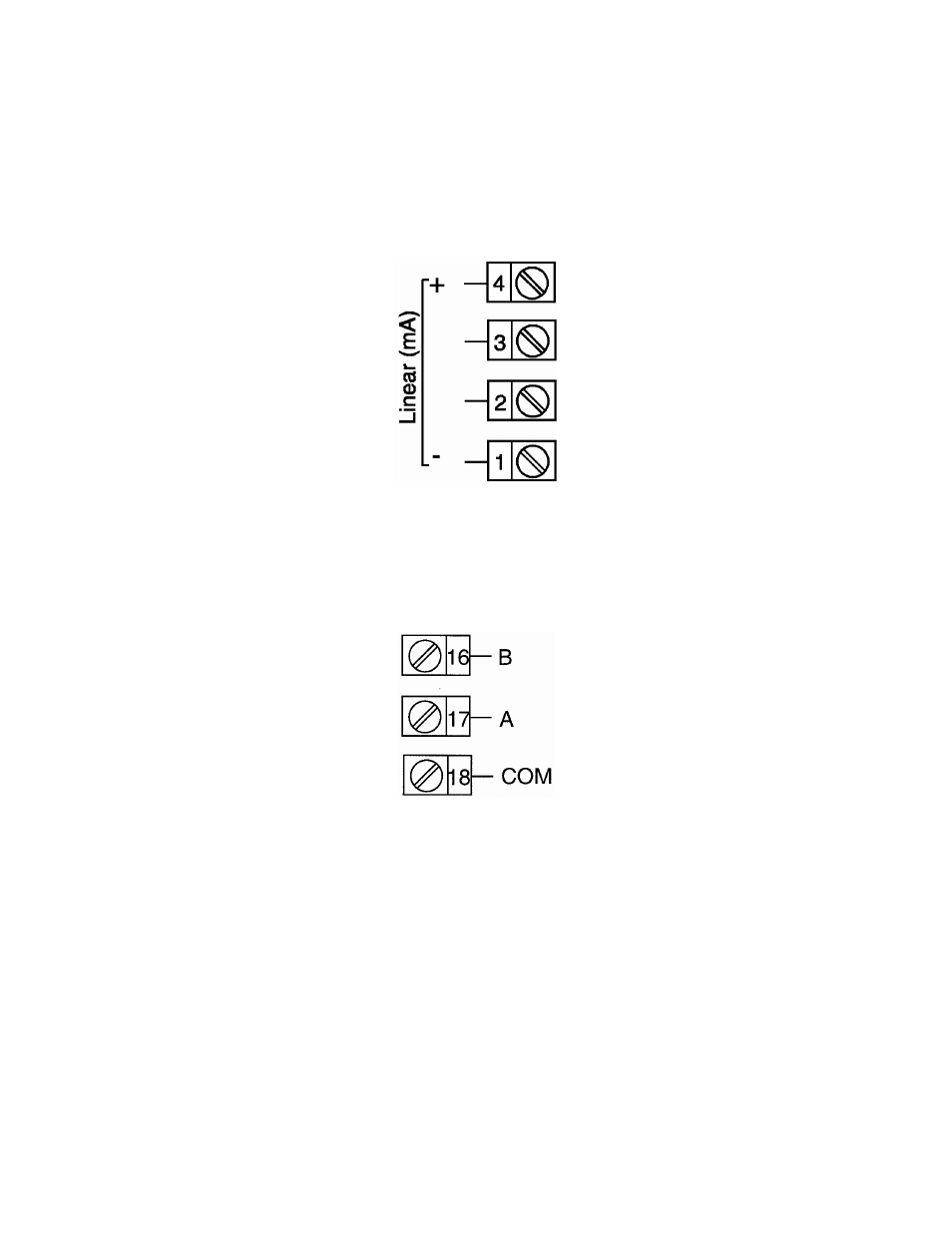
FIGURE 2-11
mADC Input
Make mADC connections as shown below. Terminal 4 is positive and terminal 1 is
negative. Input conditioning jumper must be positioned correctly (see Appendix B) and
Hardware Definition Code must be correct (see Section 10).
FIGURE 2-12
Remote Digital Communications - RS485
Make digital communication connections as illustrated below.