2 connecting the rs-485 port, 3 connecting the relays, Connecting the rs-485 port – Kramer Electronics RC-8iR User Manual
Page 51: Connecting the relays, Figure 51: rs-485 port wiring, Figure 52: relay wiring, Table 13: relay pinout
Installation of the RC System
47
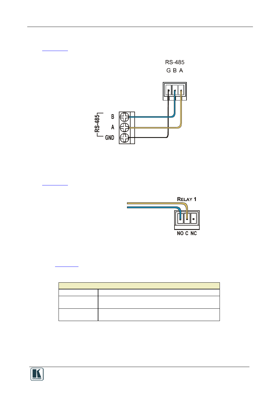
13.2 Connecting the RS-485 Port
shows how to connect the RS-485 terminal block connector
Figure 51: RS-485 Port Wiring
13.3 Connecting the Relays
shows how to connect the relays.
To Room
Items
Figure 52: Relay Wiring
On each 3-pole terminal block connector, connect either: C to NO, or C to
NC.
Table 13: Relay PINOUT
RELAY PINOUT
C
Common
NO
Normally Open (relay is open by default and closes for
activation)
NC
Normally Closed (relay is closed by default and opens for
activation)