13 installation of the rc system, 1 connecting the rs-232 port, Installation of the rc system – Kramer Electronics RC-8iR User Manual
Page 50: Connecting the rs-232 port, Figure 49: rs-232 pinout connection, Figure 50: rs-232 port wiring, Table 12: rs-232 pinout connection
KRAMER: SIMPLE CREATIVE TECHNOLOGY
Installation of the RC System
46
13 Installation of the RC System
After connecting the RC system components, connect a 12V DC power
supply to the terminal block connector, taking care that polarity is correct.
To achieve the best performance:
• Connect only good quality connection cables, thus avoiding
interference, deterioration in signal quality due to poor matching,
and elevated noise- levels (often associated with low quality cables)
• Avoid interference from neighboring electrical appliances and position the
RC system away from moisture, excessive sunlight and dust
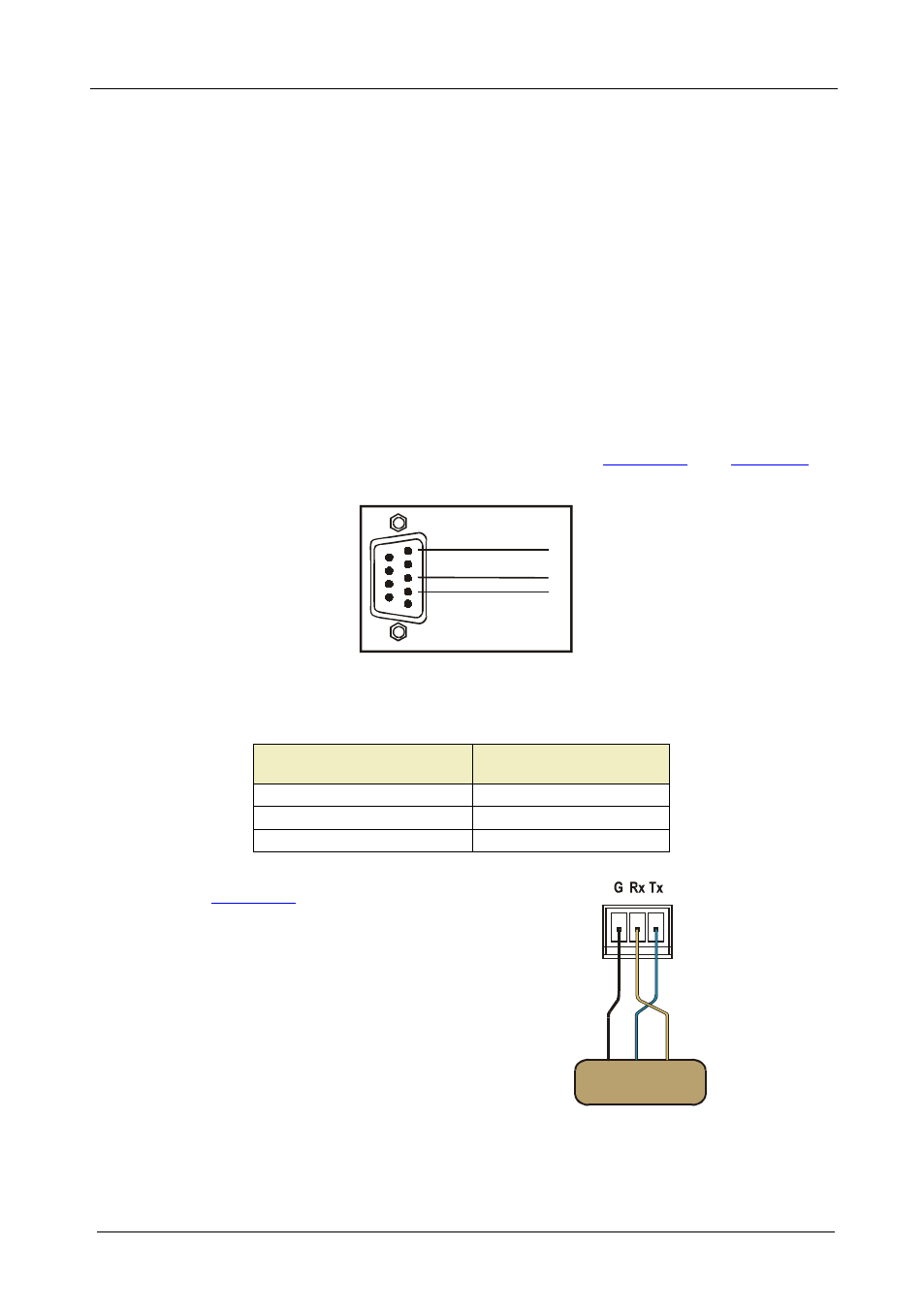
13.1 Connecting the RS-232 Port
The RS-232 9-pin D-sub connector port is defined in
RS-232 PINOUT
Rx
GND
1
2
3
4
5
6
7
8
9
Tx
Figure 49: RS-232 PINOUT Connection
Table 12: RS-232 PINOUT Connection
Connect this PIN on the
Terminal Block Connector:
To this PIN on the 9-PIN
D-SUB Connector
Tx
PIN 2
Rx
PIN 3
GND
PIN 5
connect the RS-232
terminal block connector
port for bidirectional
communications.
Peripheral Device
RS-232 Port
G Rx Tx
Figure 50: RS-232 Port Wiring