Kramer Electronics VS-3232V User Manual
Page 26
KRAMER: SIMPLE CREATIVE TECHNOLOGY
Connecting the Video Matrix Switcher
22
6.4.2
Connecting the RS-485 Control Interface
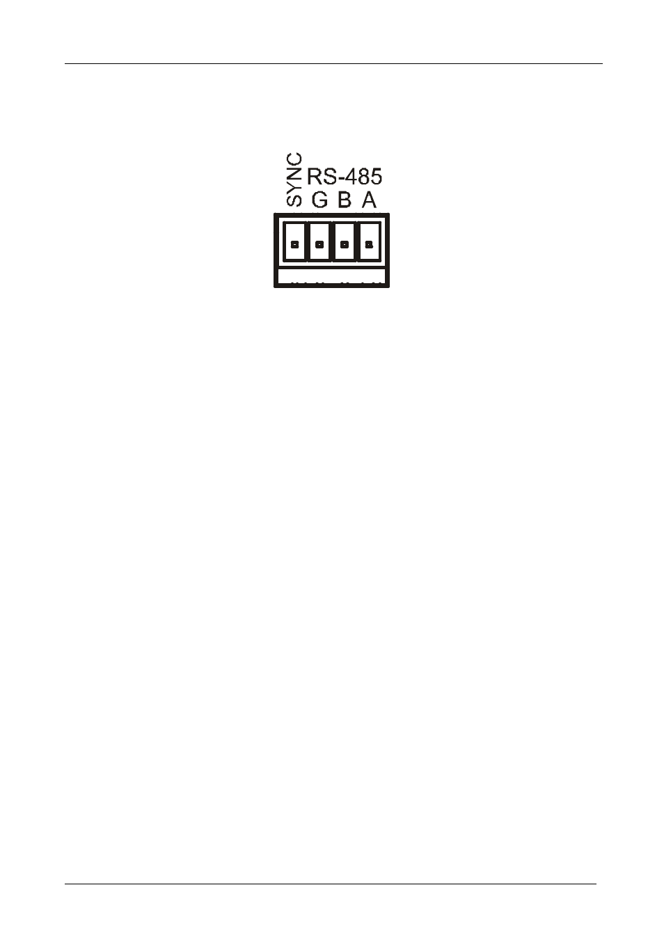
Figure 8 defines the RS-485 connector PINOUT for external RS-485 control.
The RS-485 connector is also used (if required) for vertical sync:
Figure 8: RS-485 Connector PINOUT
To connect an RS-485 connector on one
VS-3232V unit to an RS-485
connector on one or more other switchers (from the series of 32x32 or 16x16
matrix switchers), as Figure 9 illustrates:
1. Connect the “A” PIN on the first
VS-3232V unit to the “A” PIN on the second
VS-3232V unit and all the other units.
2. Connect the “B” PIN on the first
VS-3232V unit to the “B” PIN on the second
VS-3232V unit and all the other units.
3. If shielded cable is used for an RS-485 connection, you may connect the shield
to the “G” (ground) PIN.
For details about how to configure the vertical sync (if required), refer to
section 6.5 and section 8.1.
- VM-216H (25 pages)
- VM-28H (23 pages)
- VM-22H (12 pages)
- VM-24H (23 pages)
- VM-24HC (21 pages)
- VM-24HD (10 pages)
- VM-24HDCP (19 pages)
- VM-42 (8 pages)
- VP-222K (10 pages)
- VP-242 (8 pages)
- VP-32K (13 pages)
- VS-202YC (23 pages)
- 4x1S (15 pages)
- 4x1V (12 pages)
- 6241HDxl (10 pages)
- 6241N (10 pages)
- 6502 (12 pages)
- PT-201VGA (8 pages)
- TailorMade (21 pages)
- TailorMade (22 pages)
- VP-1201 (50 pages)
- VP-12x8 (34 pages)
- VP-1608 (46 pages)
- VS-88SDI (42 pages)
- VP-321xl (37 pages)
- VP-16x18AK (60 pages)
- VP-201xl (8 pages)
- VP-211K (15 pages)
- VP-27 (32 pages)
- VS-66HN (25 pages)
- VS-88HDxl (43 pages)
- VP-28 (42 pages)
- VP-2x2 (17 pages)
- VP-31 (25 pages)
- VP-311DVI (20 pages)
- VS-88HD (21 pages)
- VS-88HD (44 pages)
- VP-31KSi (16 pages)
- VP-81KSi (51 pages)
- VP-31KSi (48 pages)
- VP-41 (8 pages)
- VP-411DS (22 pages)
- VS-81HDxl (25 pages)
- VP-4x1CS (39 pages)
- VP-4x4K (61 pages)