HID VertX V100, V200, V300, V1000, and V2000 Installation Guide User Manual
Page 9
VertX Installation Guide
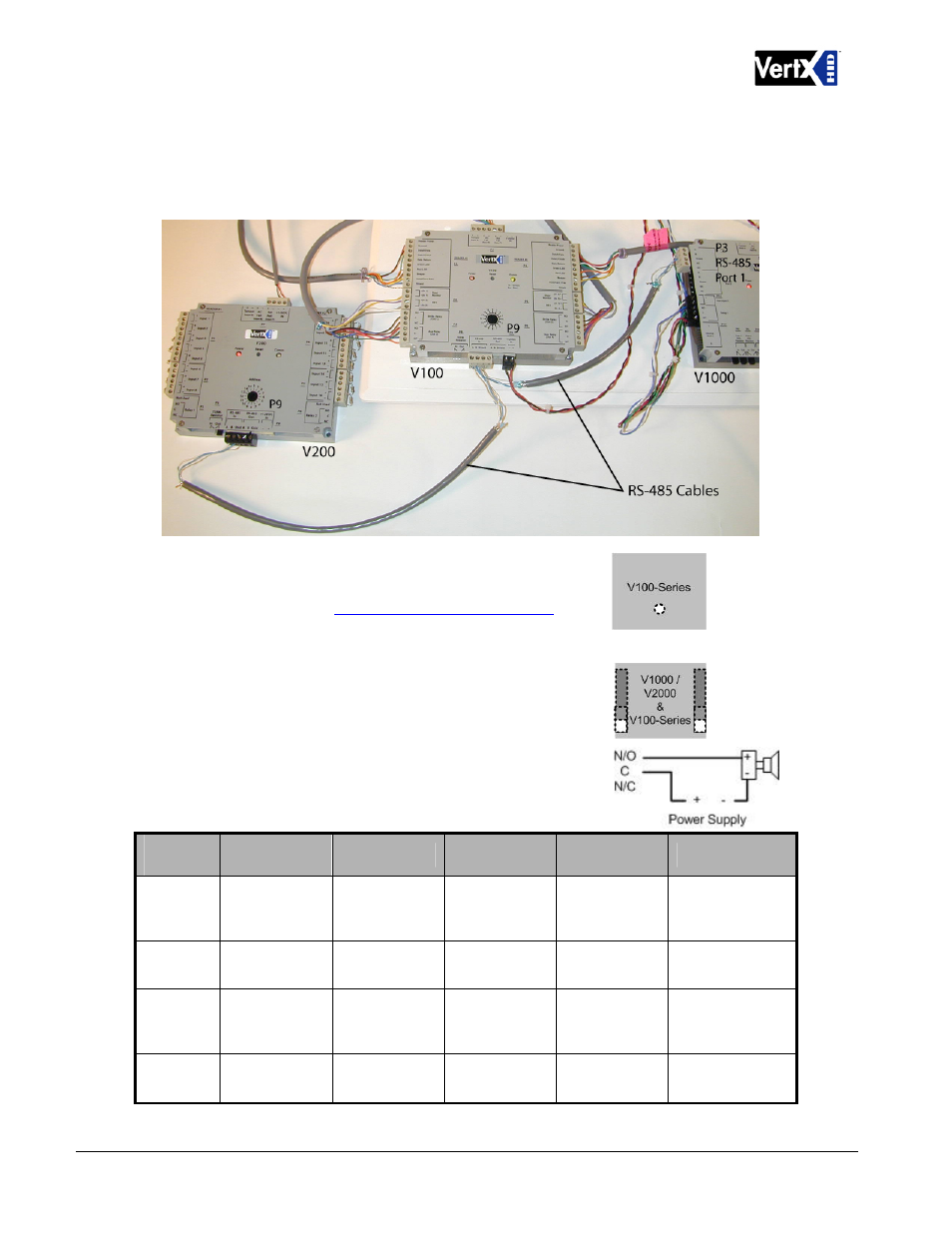
It is recommended to wire the RS-485 to the In position of the P9 terminal block of the V100-Series
panel. This is especially important when the RS-485 communication is in a “daisy chain”
configuration. If the RS-485 is wired In and Out, and power is lost, or the P9 terminal block is
unplugged on a V100-Series panel, RS-485 communications will be lost to downstream V100-Series
panels.
6. Interface
Address
– Set the interface address by turning
the Address dial. Ensure that the V100 Interface Address
is documented in the
Hardware Installation Worksheet
.
7. Output Connections (All VertX units) –
All Output
connections are used for general purpose controls. The
following table shows where the various outputs are
located. Pin numbers shown use the convention
“NO/C/NC”. For example, Output 1, V2000: P3 Pin1 is NO
(Normally Open,) Pin 2 is C (Common,) and Pin 3 is NC
(Normally Closed).
Note:
Relays are dry contact rated for 2Amps @ 30VDC.
Output
number
V2000
V1000
V100
V200
V300
1
P3 Pins 1/2/3
Strike(lock)
Relay 1
P14 Pins 3/4/5
P3 Pins 1/2/3
Strike (lock)
Relay 1
P3 Pins 2/3/4
P1 Pins 1/2/3
2
P3 Pins 4/5/6
Aux Relay 1
P11 Pins 3/4/5
P3 Pins 4/5/6
Aux Relay 1
P6 Pins 3/2/1
P1 Pins 4/5/6
3
P6 Pins 6/5/4
Strike (lock)
Relay 2
P6 Pins 6/5/4
Strike (lock)
Relay 2
P1 Pins 7/8/9
4
P6 Pins 3/2/1
Aux Relay 2
P6 Pins 3/2/1
Aux Relay 2
P2 Pins 1/2/3
December 2010
Page 9 of 24
© 2003 - 2010 HID Global Corporation. All rights reserved.