5 wiring vertx, Wiring vertx – HID VertX V100, V200, V300, V1000, and V2000 Installation Guide User Manual
Page 7
VertX Installation Guide
1.5 Wiring VertX
CAUTION: Connectors on the VertX devices are positioned to be mirror images and are not
interchangeable once the installation is complete. Therefore, you cannot unplug a
connector from one side and plug it into the corresponding connector on the other side.
1. Network Connection: Connect the VertX V1000/V2000 to the network using a standard Cat5
network patch cable. Connect one end of the Cat5 network patch cable to the J1 (RJ-45) connector
on the V1000/V2000 and the other end to the network connection point (network jack, hub, switch,
or router) on your site.
2. Serial (RS-232) Adapter cable (P/N 70007)
The Serial Adapter cable is a six inch adapter that converts the 9 pin MTA header to a standard DB-9 male
connector. This adapter is to be utilized for attaching a standard RS-232 serial modem cable (not included)
to the VertX controller. This will allow one of the approved external modems (listed in 1.6.1 Modem Setup
Requirements, page 12) to be attached to the VertX V1000.
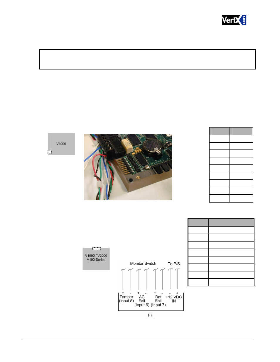
The table shows the P17 pin settings.
Pin #
P17
Pin #
P7
1 +12VDC
2 Ground
3
Bat Fail -
4
Bat Fail +
5
AC Fail -
6
AC Fail +
7 Tamper
-
8 Tamper
+
1 DCD
2 RX
3 TX
4 DTR
5 GND
6 DSR
7 RTS
8 CTS
9 RI
3. Power and Alarm input connections (All VertX units): Connect power by providing 12VDC to the
P7
connector. +12VDC goes to Pin 1 and ground to Pin 2. Batt
Fail, AC Fail, and Tamper switch inputs are wired as shown in
the table. Connect the Bat Fail and AC Fail inputs to battery
low/failure and AC failure contacts provided on the power
supply. Connect the Tamper input to a tamper switch on the
enclosure.
December 2010
Page 7 of 24
© 2003 - 2010 HID Global Corporation. All rights reserved.