HID VertX V100, V200, V300, V1000, and V2000 Installation Guide User Manual
Page 8
VertX Installation Guide
Pin #
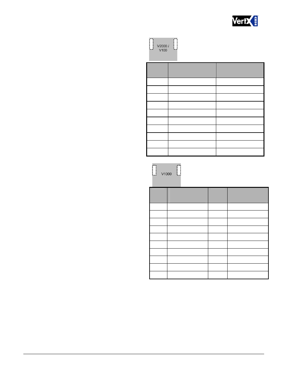
4 Reader Connections (V2000 or V100):
Connect Wiegand or clock-and-data
interfaces to a V2000 or V100 using the
connection table shown. You can connect
up to 10 signal lines for the reader. Use
as many of the signal lines as required for
your reader interface.
V2000 and V100
V2000 and V100
P4
P1
Note:
Connect the data return line to the
same ground as the reader power if the
reader is not powered by the VertX units
12VDC.
1
Reader Power
Shield Ground
2 Ground
Hold
3
Data 0 / Data
Beeper
4
Data 1 / Clock
Red LED
5
Data Return
Green LED
6
Green LED
Data Return
7
Red LED
Data 1 / Clock
8
Beeper
Data 0 / Data
9 Hold
Ground
10
Shield Ground
Reader Power
5. RS-485 Connections – The V1000
has two - RS-485 connectors and uses
the 10-pin connector on P3 and P4.
Each RS-485 bus can support a
maximum of 16 V100-Series panels
using one or two ports.
PCB
Pin #
V1000 P3
(port 1 and 2)
PCB
Pin #
V1000 P4
(port 3 and 4)
Having two ports on each bus provides
the option of splitting each RS-485 bus
into two physical connections, allowing a
total of four physical connections for the
two busses.
1
A
1
Not in use
2
B
2
Not in use
3 Shield
3 Shield
4
Not in use
4
B
RS-485 busses must be connected in a
daisy chain topology and not a star
topology.
5
Not in use
5
A
6
A
6
Not in use
7
B
7
Not in use
The V1000 termination jumper should
be in the Out position if there are no
panels attached to the port. If there are
downstream panels attached then the
termination jumper should be in the In
position.
8 Shield
8 Shield
9
Not in use
9
B
10
Not in use
10
A
CAUTION:
The V1000 RS-485 Ports 1 & 2 (P1) are a common bus and therefore cannot have
panels with duplicate Interface Addresses assigned. The same is true of the V1000 RS-485,
Ports 3 & 4 (P4). For example, two panels, both with Interface Address 0 (factory default),
cannot be connected to Ports 1 and/or 2 (P1).
December 2010
Page 8 of 24
© 2003 - 2010 HID Global Corporation. All rights reserved.