2 getting started, 1 theory of operation, Getting started – HID Hi-O iCLASS Installation Guide User Manual
Page 6: Theory of operation
iCLASS OEM75 Integration Guide, 3141-907, Rev. B.0
Page 6 of 49
January 2014
HID GLOBAL CONFIDENTIAL AND/OR PROPRIETARY INFORMATION. This document contains confidential and/or proprietary
information, which may not be duplicated, published, disseminated or disclosed, or used for any purpose, without the written
consent of HID Global Corporation. If you are an unintended recipient of this information or are unwilling to accept the above
restrictions, please immediately return this document to HID Global Corporation, 15370 Barranca Pkwy, Irvine, CA 92618-3106.
2 Getting Started
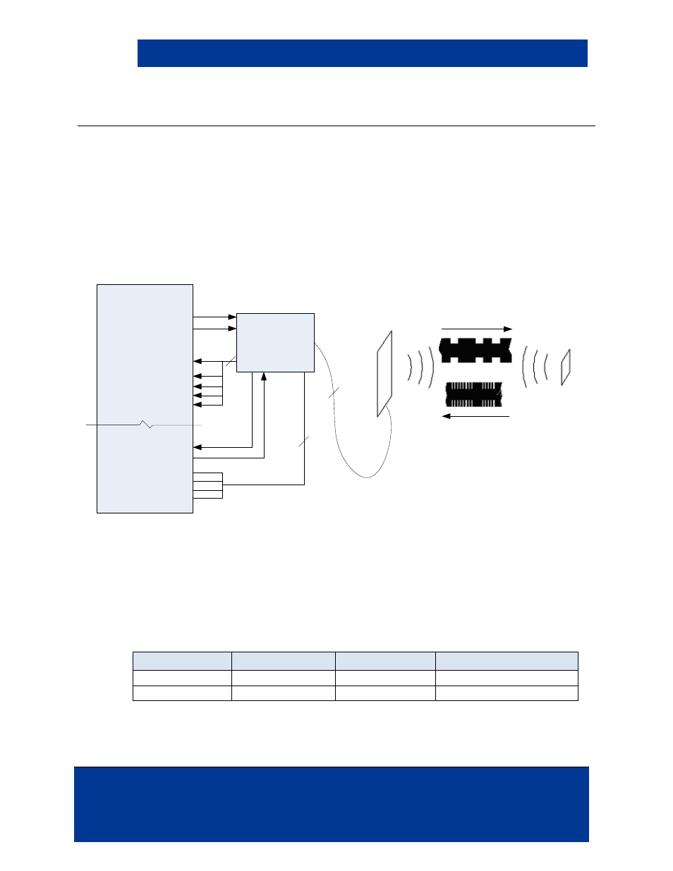
2.1 Theory of Operation
Configurable operation modes include:
•
Autonomous – In this mode, the module polls for a card constantly and will not accept
serial commands unless a card is in the field. Autonomous is the default operation of the
OEM75.
•
API – The module acts the same as in Autonomous operation except the module is always
ready to receive a command from the host. When an RF or Serial command is received,
the module will wait a configurable amount of time before it returns to polling for a card.
Figure 2-1: OEM75 Operation
Power Modes Include:
•
Ultra Low Power – The module is in Ultra Low Power mode as it polls for a card. When a
card is detected in the RF field, the module wakes up, reads the card data, changes the
Card Present line, outputs the card data, and goes back to sleep within a configured period
of time to conserve power. Use this mode with battery power.
•
Standard – The module is constantly powered on and polling for cards. The module is
never asleep in this mode. Use this mode with an external power supply.
Power
Autonomous Mode Remote Mode
Autonomous Remote Mode
Ultra Low Power
Standard Power
OEM75 Module
OEM75
Antenna
iCLASS
Card
/RESET
/HOLD
/GREEN_LED_
CARD_PRESENT
Host Hardware/Application
Wiegand Data 0
Wiegand Data 1
/BEEPER
/RED_LED
UART RX
UART TX
I
2
C SCLK / SPI_ CLK
SPI_CS
SPI_MISO
I
2
C CSDA / SPI_MOSI
4
4
5