5 wiegand, 6 serial, Wiegand – HID Hi-O iCLASS Installation Guide User Manual
Page 43: Serial
iCLASS OEM75 Integration Guide, 3141-907, Rev. B.0
January 2014
Page 43 of 49
HID GLOBAL CONFIDENTIAL AND/OR PROPRIETARY INFORMATION. This document contains confidential and/or proprietary
information, which may not be duplicated, published, disseminated or disclosed, or used for any purpose, without the written
consent of HID Global Corporation. If you are an unintended recipient of this information or are unwilling to accept the above
restrictions, please immediately return this document to HID Global Corporation, 15370 Barranca Pkwy, Irvine, CA 92618-3106.
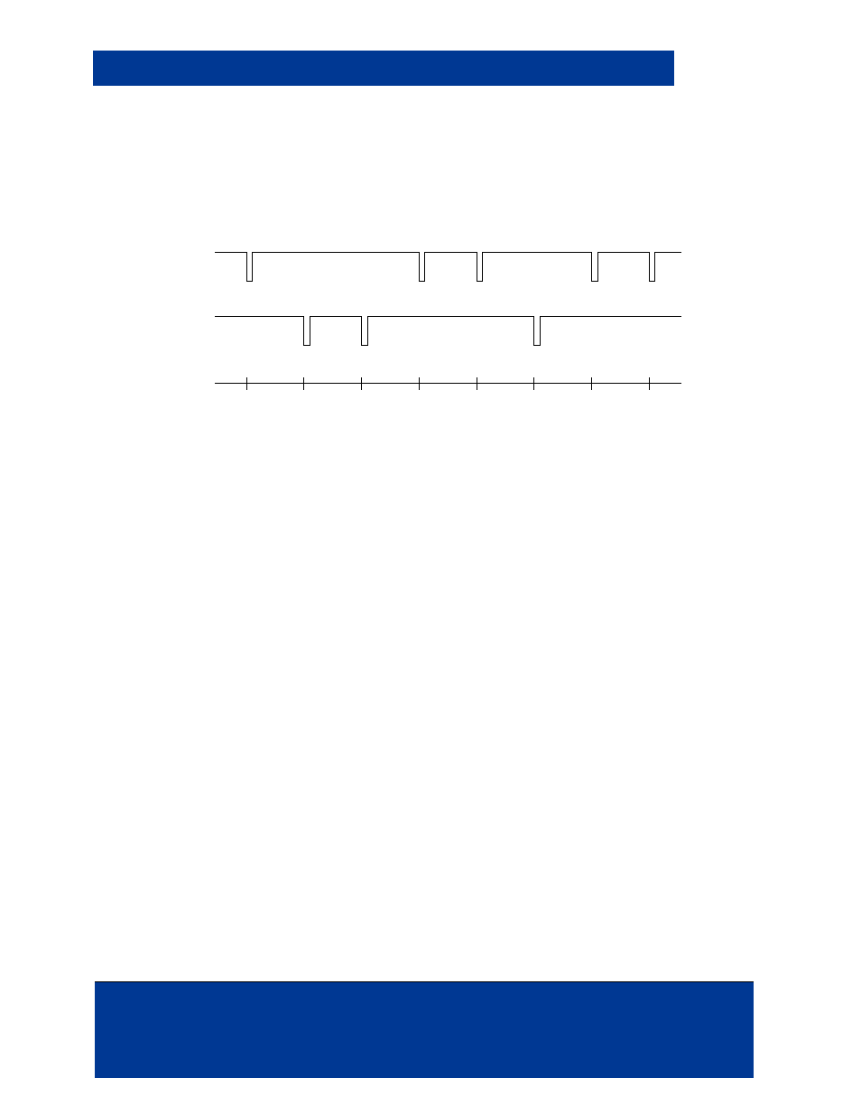
6.8.5 Wiegand
The Wiegand output port is a two wire serial interface where logic 0 data bits are transmitted on the
“Data 0” wire and logic 1 data bits are transmitted on the “Data 1” wire. The following diagram gives
an example of a Wiegand transmission using factory default settings.
DATA 0
DATA 1
T = 0
Bit = 0
T = 2ms
Bit = 1
T = 4ms
Bit = 1
T = 6ms
Bit = 0
T = 8ms
Bit = 0
T = 10ms
Bit = 1
T = 12ms
Bit = 0
T = 14ms
Bit = 0
5V
GND
5V
GND
Time
Transmission of the Data Byte 64h
MSB
LSB
Figure 611: Wiegand Transmission – Factory Settings
When no data is transmitted, the outputs are high (3.3 VDC). Data bits are represented by low-
going pulses, with an interval of time between each pulse. In the factory default configuration, the
pulse width is 40us and the spacing between pulses is 2ms. Pulse width is configurable in 4us
intervals with values ranging between 4us and 1.02ms. Pulse spacing is configurable in 25us
intervals with values ranging between 25us and 6.375ms.
Specifications for the Wiegand communication protocol are detailed in the Security Industry
Association document SIA AC-01 (1996.10), Wiegand Card Reader Interface Standard. The
OEM75 is not SAI voltage compliant. HID does not support the development of an RFID reader
unless specifically specified under the CPPA and NDA articles.
The OEM75 module is intended to add RFID reader functionality to a host device. The device in
which the OEM75 integrated must translate the 3 VDC module Voh signaling to 4 to 5.5 VDC Voh
SIA AC-01 (1996.10) signaling requirements.
6.8.6 Serial
Current serial hardware interfaces for the OEM75 include a UART with RX and TX signals, a four
wire SPI slave communication port using /Chip Set, Clock, MOSI, MISO, or I
2
C.