4 p1 connector ping mode static states, 5 electrical application hints, P1 connector ping mode static states – HID Hi-O iCLASS Installation Guide User Manual
Page 22: Electrical application hints
iCLASS OEM75 Integration Guide, 3141-907, Rev. B.0
Page 22 of 49
January 2014
HID GLOBAL CONFIDENTIAL AND/OR PROPRIETARY INFORMATION. This document contains confidential and/or proprietary
information, which may not be duplicated, published, disseminated or disclosed, or used for any purpose, without the written
consent of HID Global Corporation. If you are an unintended recipient of this information or are unwilling to accept the above
restrictions, please immediately return this document to HID Global Corporation, 15370 Barranca Pkwy, Irvine, CA 92618-3106.
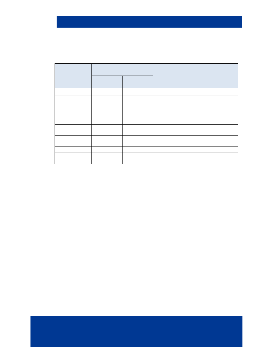
5.4 P1 connector Ping Mode Static States
For Ultra Low Power mode to operate optimally at the lowest power, the following levels are
recommended for the Host Circuitry static signal states.
Pin Name
Signal Levels in Ultra Low
Power
Application Comments
OEM75
Circuit
Host Circuit
+3.3 VDC
0.0 VDC
0.0 VDC
The +3.3 VDC read is shut off in this mode
Ground
0.0 VDC
Ground or
0.0VDC
This signal is required for all relative
voltages
SPI Clock
Input
Output - low
/SPI_CS
Input
Output - low
OEM75 has 10K Pull-Up resistor to
switched off 3.3V
/SPI Data In
Input
Output - low
OEM75 has 10K Pull-Up resistor to
switched off 3.3V
/SPI Data Out
Output – low /
float
Input
Host must have State set low for meta-
stability protection
UART RX
Input
Output - low
OEM75 has 10K Pull-Down resistor
UART TX
Output – low /
float
Input
Host has State set low for meta-stability
protection
5.5 Electrical Application Hints
The following provides hints for antenna applications.
•
The pins are pre-soldered into the antenna holes and strain relieved by an adhesive.
•
The ribbon should not be folded with a hard crease (radius defined at < 3mm) like a piece
of paper more than once; for example if creased at 1mm never unfold it.
•
The ribbon performs best as placed in free space. To avoid detuning the antenna from
optimal Ultra-Low Power performance, do not attach the ribbon to a metal surface. Observe
capacitive couplings near proximity to metallic surfaces within 10mm.
•
If a ribbon cable is damaged it can only be field replaced by the exact type and length item.
•
The SUMI-CARD
®
ribbon used has a 0.1mm copper thickness for better signal conduction.
•
The electrical connection between the antenna and connector is not air-tight. It is
recommended that the connector or entire module be sealed to avoid oxidation.
•
Linear power supply is recommended to reduce input noise.