5 electrical specifications, 1 power supply, 2 electrical connections – HID Hi-O iCLASS Installation Guide User Manual
Page 18: Electrical specifications, Power supply, Electrical connections
iCLASS OEM75 Integration Guide, 3141-907, Rev. B.0
Page 18 of 49
January 2014
HID GLOBAL CONFIDENTIAL AND/OR PROPRIETARY INFORMATION. This document contains confidential and/or proprietary
information, which may not be duplicated, published, disseminated or disclosed, or used for any purpose, without the written
consent of HID Global Corporation. If you are an unintended recipient of this information or are unwilling to accept the above
restrictions, please immediately return this document to HID Global Corporation, 15370 Barranca Pkwy, Irvine, CA 92618-3106.
5 Electrical Specifications
5.1 Power Supply
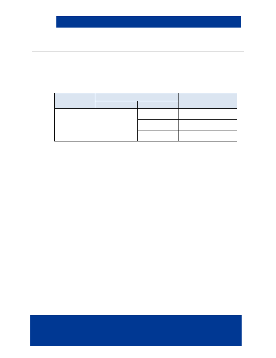
The following table specifies necessary power supply specifications.
Table 5-1: I/O Electrical Specifications
Pin Name
Parameters
Notes
Voltage
Current
Battery Positive
to
Ground
4.0 VDC
to
10.0 VDC
40mA +/- 3mA
Nominal
Reader mode (no card)
current
80mA +/- 5mA
Peak
Card reading current
12uA +/-3uA
Ultra-Low Power Mode (no
card) current
Note: If implementing the OEM75 in a UL listed product, UL requires voltage range tolerances
of -15% to +10%.
5.2 Electrical Connections
The OEM75 is designed for a host with 3.3 VDC or 5.0 VDC I/O interfacing. All input signals to the
OEM75 are 5 VDC tolerant. All output signals are open collector; except the Wiegand lines have a
1K pull up to a diode isolated +3.3 VDC.
For the P1 connector signals, the input interface logic levels are the following specifications for
output logic levels.
< 0.5 VDC for Vil
> 2.0 VDC for Vih
< 0.4 VDC for Vol
> 2.4 VDC for Voh
External LED’s can be added to the board by connecting the LED pins located next to the beeper
on the upper left portion of the board (see Figure 4-1 – OEM75 – 3141Axx). The LEDs can be
controlled with serial commands or using the LED control lines listed in the following table.
CAUTION: Install a 1K Ohm serial resistor on the SPI lines in SPI communication mode to
eliminate negative voltage spikes.