3 antennas, Antennas – HID Hi-O iCLASS Installation Guide User Manual
Page 14
iCLASS OEM75 Integration Guide, 3141-907, Rev. B.0
Page 14 of 49
January 2014
HID GLOBAL CONFIDENTIAL AND/OR PROPRIETARY INFORMATION. This document contains confidential and/or proprietary
information, which may not be duplicated, published, disseminated or disclosed, or used for any purpose, without the written
consent of HID Global Corporation. If you are an unintended recipient of this information or are unwilling to accept the above
restrictions, please immediately return this document to HID Global Corporation, 15370 Barranca Pkwy, Irvine, CA 92618-3106.
4.3 Antennas
Basic Antenna Operation
Credentials obtain their power from the magnetic field generated by the antenna of the reader. At
the operating frequency of the reader this interaction is similar to the operation of an air core
transformer. When an antenna is energized by an alternating current the induced magnetic field is
directly proportional to the area enclosed by the antenna loop. The larger the loop, the more
excitation current is required to produce the same level of magnetic flux. That flux covers a larger
area and so the read range is extended. Other external factors can affect the magnitude of this
induced magnetic field. Magnetic lines of flux when generated by a loop antenna are oriented
perpendicular to the plane of the loop. This is known as the right-hand rule, the magnetic field wraps
around the wire in the direction of current flow.
The antennas for the OEM75 are available in two different configurations.
•
Non-tuned
Non-tuned antennas do not have tuning components loaded. OEM customers must stuff
parallel and series capacitance in order to custom-tune non-tuned antennas to their specific
environment. There are many factors involved with antenna tuning regarding proximity to
metal and electronics. HID Global can provide assistance with tuning antennas for custom
OEM environments. Contact your local HID Connect Technical Support for details.
•
Air-tuned
Air-tuned antennas do have tuning components loaded. The antenna is pre-tuned for open
air conditions (for example, not near metal). When an air-tuned antenna is placed near
metal, its tuning is affected causing it to perform with a slightly smaller read range. More
importantly, communication errors become more frequent when large data transfers are
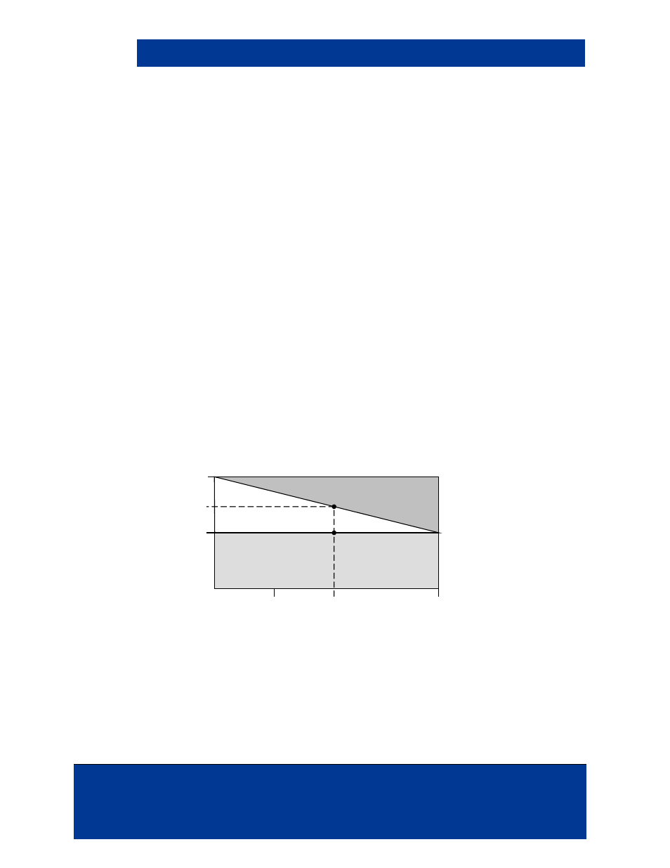
involved. All air-tuned antennas are pre-tuned for a 4.0 in (101 mm) cable length. For cable
lengths of differing sizes, reference the following graph for read range impacts.
Figure 4-3: Power Modes and Air-tuned Antenna (3142)
Match the signal and ground connections from the antenna to the OEM75 module with a ribbon
cable (1.25mm spacing).
Due to power requirements, applications requiring PIV smart card support require a larger antenna.
The environment where the antenna is placed and tuning also affect the performance. Consult
Connect Technical Support for assistance in choosing an antenna for your environment.
3.0 in
[78 mm]
2.3 in
[60 mm]
R
ea
d
R
an
ge
1.5 in
[40 mm]
4.0 in
[101 mm]
6.0 in
[160 mm]
Cable Length
Standard P
ower
Ultra Low
Power Mode
2.7 in
[70 mm]