HID Hi-O iCLASS Installation Guide User Manual
Page 19
iCLASS OEM75 Integration Guide, 3141-907, Rev. B.0
January 2014
Page 19 of 49
HID GLOBAL CONFIDENTIAL AND/OR PROPRIETARY INFORMATION. This document contains confidential and/or proprietary
information, which may not be duplicated, published, disseminated or disclosed, or used for any purpose, without the written
consent of HID Global Corporation. If you are an unintended recipient of this information or are unwilling to accept the above
restrictions, please immediately return this document to HID Global Corporation, 15370 Barranca Pkwy, Irvine, CA 92618-3106.
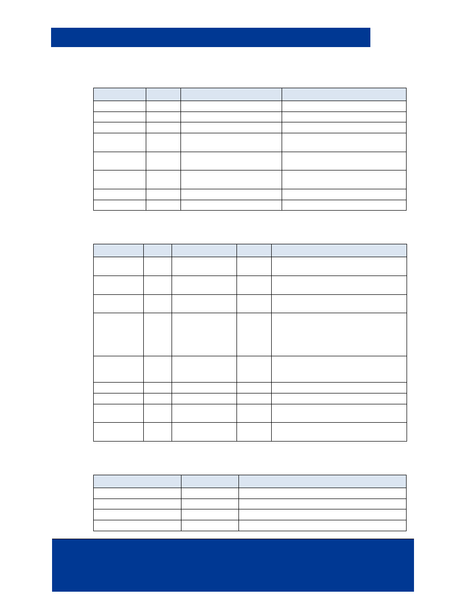
Table 5-2: P1 Connector I/O Functionality
Connection
Pin #`
Signal Name
Function
P1
1
+3.3 VDC
0.1W max Power sourced output
P1
2
Ground
Logic level reference
P1
3
SPI Clock / (I2C SCLK)
Clock signal for either SPI or I2C
P1
4
/SPI Chip Select
Active Low signal to select the SPI
chip
P1
5
SPI Data In (I2C_SDA)
SPI Data Line valid when clock signal
transitions.
P1
6
SPI Data Out
SPI Data Line valid when clock signal
transitions
P1
7
UART Receive
Serial Input Line
P1
8
UART Transmit
Serial Output Line
Table 5-3: P2 Connector I/O Functionality
Connection
Pin #` Signal Name
I/O
Function
P2
1
Supply Voltage
Positive (V+)
Input
Power Supply Positive Voltage
P2
2
Supply Voltage
Negative (V-)
Input
Power Supply Ground
P2
3
/Reset
Input
Active Low signal which resets the OEM
75.
P2
4
/Hold
Input
Active Low signal which holds off
presentation of card data. When
asserted, this line either buffers a card or
disables a card read until released, as
configured.
P2
5
/Green LED and
Card Present
Output
The signal on this pin, reflects the
recognition of a card in the vicinity of the
antenna.
P2
6
Wiegand Data 0
Output
Internal 1K to +3.3VDC & Collector
P2
7
Wiegand Data 1
Output
Internal 1K to +3.3VDC & Collector
P2
8
/Beeper
Output
Active Low signal which enables off
board signaling
P2
9
/Red LED
Output
Active Low signal which can be used to
enable an off board Red LED
Table 5-4: P3 Connector I/O Functionality
Connection
Pin #`
Pin Name
P3
1
Antenna
P3
2
Antenna Feedback
P3
3
Ground 1
P3
4
Ground 2